Structure Configuration
Structure is the structural modeling page in Dreapex TMM. It defines the incidence medium, the optical stack itself, and the transmission medium. This page determines the object to be solved; if the structure is invalid, Run, Run Sweep, and Run Optimizer may still be visible, but the model will not produce a usable result.
This chapter defines a practical method for building valid thin-film models. It covers top-level stack editing, refractive-index models, Layer Group, surrounding media, and structure validation.
Page Structure and Setup Order
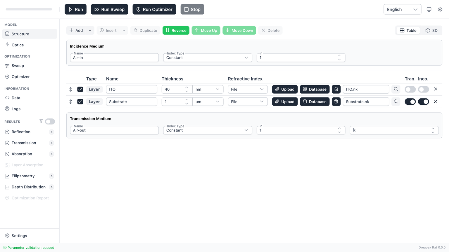
The Structure page contains four functional regions:
| Region | Main content | Engineering role |
|---|---|---|
| Page toolbar | Add, Insert, Duplicate, Reverse, Move, Delete, RI Status, Table / 3D | Manage top-level structure elements, RI database status, and view mode |
| Incidence-medium panel | Incidence Medium | Define the incoming boundary condition |
| Structure table | Top-level layers, groups, and parameter editors | Define the optical stack itself |
| Transmission-medium panel | Transmission Medium | Define the outgoing boundary condition |
The footer status bar updates continuously while you edit. The correct editing rhythm is: make one round of changes, then check the footer once, rather than making many changes and debugging them only at the end.
Structure setup order:
- Confirm
Incidence Mediumfirst. - Edit normal layers or create a
Layer Group. - Adjust the stack order if needed.
- Configure
Transmission Mediumlast. - Move to
Opticsonly after the footer status returns to passed.
This order reduces rework because index models, incoherent settings, surrounding-medium absorption rules, and layer order all interact.
Top-Level Editing: Toolbar and Structure Table
The page toolbar only controls the top-level structure table. It does not control the internal table inside the Layer Group dialog.
| Control | Purpose | Requirement | Practical recommendation |
|---|---|---|---|
Add | Append a normal layer to the end | Parameters must not be locked | Use it to extend the stack |
Add > Layer Group | Append a layer group to the end | Parameters must not be locked | Use it for periodic units or repeated blocks |
Insert | Insert a normal layer after the selected row | A row must be selected | Use it when adding a transition layer at a specific position |
Insert > Layer Group | Insert a layer group after the selected row | A row must be selected | Use it when inserting a periodic block mid-stack |
Duplicate | Copy the selected row | A row must be selected | Use it to reuse similar settings quickly |
Reverse | Reverse the top-level order | The top-level structure must be non-empty | Useful for checking reversed incidence order |
Move Up / Move Down | Move the selected row by one position | A row must be selected | Use it for fine ordering changes |
Delete | Remove the selected row | A row must be selected | Confirm that the selected row is the intended top-level target |
Table / 3D | Switch between table and 3D view | Page must be editable | Use 3D to inspect order; keep table view as the main editing mode |
If Insert, Duplicate, Move Up, Move Down, or Delete is disabled, the first thing to check is whether the target row is selected.

Click the 3D button in the toolbar to switch to 3D visualization. The 3D view provides camera presets (Front/Isometric/Dimetric/Trimetric), shape (Square/Circle), display options (Lighting/Names/Thickness/Incident Ray/Explode), and image export.
Each row in the structure table is one top-level structure element. A row can be either a normal Layer or a Layer Group. The key columns are:
| Column | Meaning | Key rule |
|---|---|---|
| Checkbox | Enable or disable the top-level element in the current calculation | At least 1 top-level element must remain enabled |
Type | Indicates whether the row is a Layer or Group | Read-only; used only for identification |
Name | Name of the top-level element | Required; top-level names must be unique |
Thickness / Repeat | Thickness for normal layers; repeat count for groups | Thickness must be > 0; repeat count must be a positive integer |
Refractive Index | Normal layers show the index model; groups show Edit Layer Group | Group internals must be edited in the dialog |
| Parameter editor | Changes with the current index model | Parameters must match the chosen model |
Transparency | Transparency flag for a normal layer | Available only for normal layers |
Incoherent | Incoherent flag for a normal layer | Available only for normal layers and restricted with birefringence |
Delete | Delete the current top-level row | Removes the top-level element, not an internal group layer |
In practical use, the structure table is governed by four rules that matter most:
- Not all top-level elements may be disabled.
- Top-level names must be unique; duplicated rows should be renamed immediately.
- Normal-layer thickness must be strictly greater than
0; if a layer should be excluded temporarily, disable it instead of setting thickness to0. Incoherentapplies only to normal layers; once enabled, that layer should not be configured as a birefringent material.
Transparency can be used to express the intended modeling role of a layer, but it does not replace physical material parameters. A transparent layer still requires valid refractive-index inputs.
Refractive-Index Model Selection
For normal layers, the parameter editor changes with the selected refractive-index model. Choosing the correct model is one of the central structural decisions on this page.
| Model | Suitable use | Required parameters | Key restriction |
|---|---|---|---|
Constant | Constant-index approximation, concept checks, rapid prototyping | n, k | n > 0, k >= 0 |
Const. Birefringence | Constant birefringent approximation, anisotropic sensitivity studies | no, ko, ne, ke | All four values must be valid; cannot be combined with incoherent mode |
File | Real wavelength-dependent material data | A file or a database material | File contents must be consistent with the selected material type |
For most work, the correct choice can be made as follows:
- For concept checks or rapid reference models, start with
Constant. - For anisotropic studies without external data, use
Const. Birefringence. - For realistic dispersion, use
File.
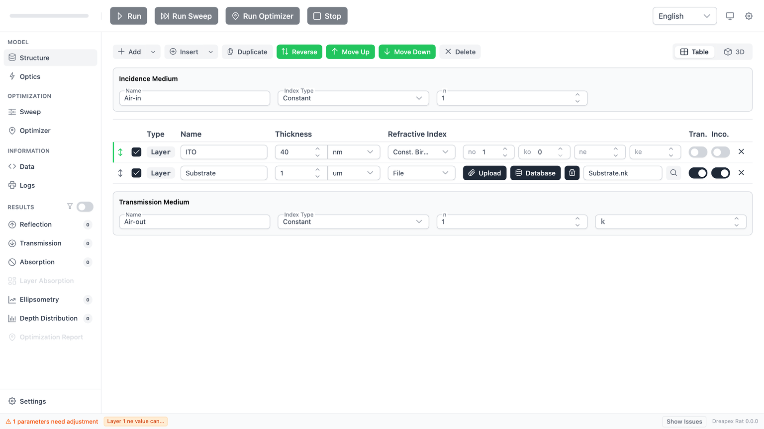
When switching to Const. Birefringence, the parameter area expands from two inputs to four. This is the clearest visual indicator that the index model changed.
In File mode, the editor exposes six controls:
| Control | Purpose |
|---|---|
Upload (paperclip icon) | Upload a local .nk / .txt refractive-index file |
Database | Open the refractive-index database dialog |
Clear (trash icon) | Clear the current refractive-index file (requires confirmation) |
| File name display | Read-only; shows the name of the currently loaded file |
Preview (magnifying-glass icon) | Open the refractive-index chart preview dialog |
Interpolation | Select interpolation method: Linear / PCHIP / Cubic Spline |
The recommended sequence is fixed: check the database first, import a local file only if needed, preview the curve before continuing, and clear the current file before replacing it.
Layer Group: Periodic Structure Modeling
When the stack contains a repeated unit, Layer Group should be used instead of manually duplicating a large number of normal layers. Typical examples are DBRs, repeated bilayers, and periodic functional units.
There are two entry points:
Add > Layer Group: append a group to the end of the top-level stack.Insert > Layer Group: insert a group after the currently selected top-level row.
The editor is identical in both cases; only the insertion position changes.
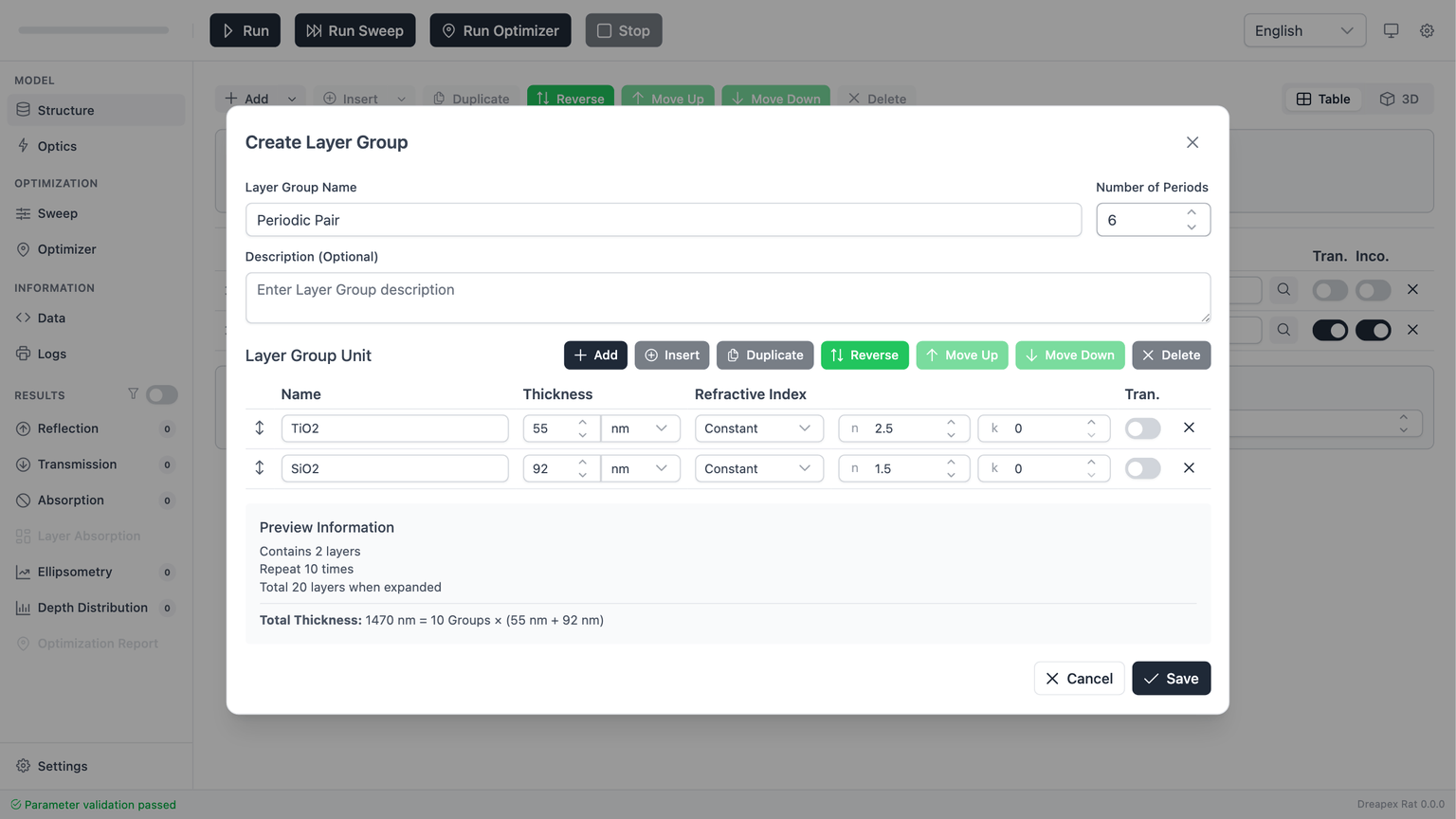
The dialog can be divided into four parts:
| Area | Content | Function |
|---|---|---|
| Basic information | Name, Repeat Count, Description | Define the identity and multiplicity of the group |
| Internal toolbar | Add, Insert, Duplicate, Reverse, move, delete | Manage internal sub-layers |
| Internal table | Names, thicknesses, index models, and parameters of sub-layers | Define one repeated unit |
| Preview summary | Internal layer count, repeated total layer count, total thickness | Quickly assess group scale |
The most important rules for a group are:
| Field | Rule | Engineering recommendation |
|---|---|---|
Name | Required; as a top-level element it must not duplicate another top-level name | Use a structural name such as DBR Pair |
Repeat Count | Must be a positive integer | Validate with a small value first, then increase |
Description | Optional | Use it to record the design purpose or periodic meaning |
One implementation detail must be remembered clearly:
- Inside the
Layer Groupdialog, theRepeat Countcontrol is limited to1-100by the UI. - After returning to the top-level structure table, the repeat count can be increased further to
1-1000. - The underlying validation logic accepts positive integers in the range
1-1000.
Therefore, if the target repeat count is above 100, the correct procedure is to create the group first and then increase the repeat count from the top-level table.
Internal editing behaves like top-level editing, but only within the current group. Internal sub-layers must still satisfy the same core rules: non-empty names, names unique within the group, thickness greater than 0, and parameters consistent with the selected index model.
Three differences matter in practice:
- Internal sub-layers expose
Transparency, but notIncoherent. - Internal reordering changes only the current group, not the top-level stack order.
- Changes are written back only when
Saveis clicked;Canceldiscards the current dialog edits.
If coherent/incoherent switching is expected to happen often, normal top-level layers are usually a better choice than putting those layers inside a Layer Group.
Surrounding-Medium Configuration
The Structure page provides Incidence Medium above the stack and Transmission Medium below it. These are boundary conditions for the stack, not layers inside the stack.
Both panels share the same baseline rules:
- The name cannot be empty.
- Only
ConstantandFileare supported as index models. - Birefringent constant mode is not supported for surrounding media.
- Birefringent refractive-index files are also not supported for surrounding media.
The practical differences are:
| Item | Incidence Medium | Transmission Medium |
|---|---|---|
| Physical role | Defines the incoming boundary condition | Defines the outgoing boundary condition |
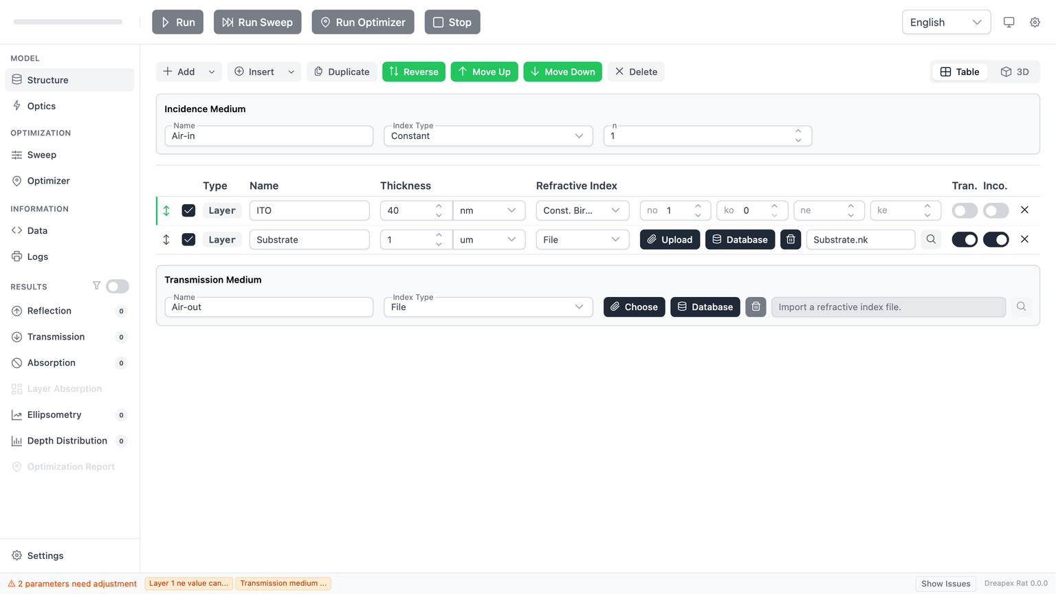
| Editable fields | Name, Index Type, n, or a file input block | Name, Index Type, n, k, or a file input block |
| Absorption rule | Must remain non-absorbing, effectively k = 0 | May be non-absorbing or absorbing |
| Database usage | Not the main database entry point | Can use the refractive-index database directly in File mode |
The most important engineering restriction is that the incidence medium must remain non-absorbing. Even in file mode, every value in the imported k column must remain 0, otherwise validation fails.
The transmission medium is the natural place to model substrates or output media. In constant mode it accepts an explicit k; in file mode it can load a material directly from the refractive-index database. Absorbing substrates and lossy output media should therefore usually be modeled on the transmission side.
Refractive-Index Database
When a normal layer or a surrounding medium uses File mode, the Database button opens the refractiveindex.info Database dialog, which provides access to the built-in refractive-index material catalog.

Dialog Layout
The dialog is divided into two panels:
| Region | Content | Purpose |
|---|---|---|
| Left panel | Material tree browser (Shelf > Book > Material hierarchy) or search result list | Locate materials by category or search |
| Right panel | Selected Material metadata + refractive-index curve preview | Verify material identity and curve shape before applying |
Search
The search bar at the top accepts material names, materialId values, or database source paths. Press Enter to jump directly to the matched material and load its preview.

Material Metadata
After selecting a material, the right panel displays:
| Field | Meaning |
|---|---|
Material ID | Unique identifier in the database |
Version | Material data version number |
Ordinary Path | Database path for the ordinary-ray data |
Extraordinary Path | Database path for the extraordinary-ray data (shown only for birefringent materials) |
Selection Workflow
- Expand
Shelf > Book > Materialin the left-panel tree, or type a keyword in the search bar and pressEnter. - Click a material entry; the right panel loads the refractive-index curve preview automatically.
- Verify the metadata and curve, then click
Confirmto apply the material to the current layer or surrounding medium. - To cancel, click
Cancelor close the dialog.
After confirmation, the layer row shows the material file name. The chart preview dialog will display a Linked to Database tag, indicating that the current data originates from the database.
Interpolation Method
When a layer or surrounding medium uses File mode, an Interpolation dropdown appears at the end of the layer row. It controls how refractive-index data are interpolated between data points.
| Option | Description |
|---|---|
Linear | Linear interpolation (default) |
PCHIP | Piecewise Cubic Hermite Interpolating Polynomial; preserves monotonicity |
Cubic Spline | Cubic spline interpolation; smoother curves but may overshoot |

Linear interpolation and recommends switching to PCHIP. With sparse data points, Linear interpolation may produce insufficiently smooth refractive-index curves that affect calculation accuracy.RI Status Check
The RI Status button in the page toolbar checks whether all database-linked layers have up-to-date refractive-index data.
Check Workflow
Clicking RI Status compares each database-linked layer against the remote database version. A toast message displays one of three states:
| State | Display |
|---|---|
| Checking | Spinner icon + "Checking N database-linked layer(s)..." |
| All up to date | Green check icon + "All RI data is already up to date" |
| Updates found | Per-layer action table showing Reason (updated or missing), version info, source, and Refresh / Detach buttons |

When updates are found, each row in the action table corresponds to a layer that requires attention:
updated: A newer version exists in the database; clickRefreshto update.missing: The material no longer exists in the latest database; onlyDetachis available to remove the database link.
Bulk Operations
The dropdown menu next to the RI Status button provides two bulk operations:
| Menu item | Effect |
|---|---|
Refresh RI from Database for All Layers | Update refractive-index data from the database for all linked layers at once |
Detach RI Database Link for All Layers | Remove database links from all layers at once, keeping the currently loaded data |
Detach removes the database link but does not delete the loaded refractive-index data. After detaching, the layer's RI data becomes a standalone file and no longer tracks database versions.Chart Preview Dialog
Click the Preview button (magnifying-glass icon) on a layer row or surrounding medium to open the refractive-index chart preview dialog.
The dialog contains:
| Section | Content |
|---|---|
| Chart area | n/k refractive-index curves for the current material |
| Description area | Editable material description text |
| Export buttons | Export TXT, Export CSV |
| Database info section | Shown only for database-linked materials: Linked to Database tag + Material ID / Version / Ordinary Path / Source |
| Database action buttons | Refresh From Database, Detach Database Link |
The chart area displays n/k refractive-index curves as a function of wavelength, allowing a quick visual check that the dispersion profile matches expectations.

For database-linked materials, the dialog footer shows a Linked to Database tag along with Refresh From Database and Detach Database Link buttons for managing the database synchronization state.

Wavelength Coverage Check
Before running a calculation (Run, Run Sweep, Run Optimizer), the software automatically verifies that the refractive-index data wavelength range of every File-mode layer and surrounding medium covers the configured wavelength sampling range.
If any layer's RI data does not fully cover the requested wavelength sampling range, the run is blocked. The error message identifies the layer name, the data coverage range, and the requested range.
Optics page.Structural Validation
The most common structural failures can be reduced to the following cases:
| Problem | Typical symptom | Corrective action |
|---|---|---|
| No active top-level element | Validation fails after all rows are unchecked | Keep at least 1 top-level layer or group enabled |
| Duplicate names | Validation fails immediately after duplication or reports duplicate names | Check top-level names first; if a Layer Group is involved, check internal names as well |
| Zero or negative thickness | A normal layer or an internal group layer cannot pass validation | Set thickness to a value greater than 0; use disable instead of 0 for temporary exclusion |
| Incoherent and birefringence conflict | Validation fails after enabling Incoherent and then choosing a birefringent model | Keep only one: either use an incoherent non-birefringent layer, or disable incoherent mode before using birefringence |
| Absorbing incidence-medium file | Validation fails after switching the incidence medium to file mode | Inspect the file and ensure the k column remains identically 0 |
Before leaving this page, the correct structural self-check is:
- At least 1 top-level element is enabled.
- Top-level names are unique.
- Every thickness value is greater than
0. - Each normal layer uses parameters consistent with its current index model.
- Both surrounding media satisfy the naming, type, and absorption constraints.
- The footer validation status has returned to passed.
Baseline Modeling Procedure
To build a standard “air / single film / substrate” model, use the following sequence:
- Keep
Incidence Mediumas a non-absorbing constant medium. - Edit the default normal layer by setting its name, thickness, and refractive-index model.
- If realistic dispersion is required, switch that layer to
Filemode and load a database material. - Configure the substrate in
Transmission Medium; if the substrate is absorbing, definekthere. - Check the footer and confirm that the structure passes validation.
- Then move to
Opticsfor angle, wavelength, and detector configuration.
For periodic structures, replace step 2 with: create a Layer Group, define one repeated unit in the dialog, and set the repeat count.
After the structure passes validation, continue with the next chapter: Optical Parameters.