Optical Parameters
The Optics page defines illumination conditions, solver range, and output targets. This chapter covers four areas:
- setup rules for wavelength mode, sampling, incident angle, polarization ratio, and cone-angle averaging;
- activation conditions for basic detectors, incident spectrum, visible color, ellipsometry, depth-resolved outputs, and dispersion detectors;
- configuration of dispersion numerical quality and interpolation recommendations;
- the most common validation conflicts that should be cleared before pressing
Run.
Page Structure and Setup Order
The Optics page is divided into six functional regions:
| Region | Main content | Role |
|---|---|---|
Common Parameters | Wavelength mode, wavelength inputs, incident angle, polarization ratio | Define the baseline illumination conditions for every calculation |
Cone Angle | Cone half-angle, distribution, ring count | Average results over a cone of incident angles |
R · T · A | Basic detectors and incident-spectrum settings | Define the standard energy outputs and spectral weighting |
Ellipsometry | Psi, Delta | Enable ellipsometric outputs |
Depth Distribution | Depth detectors and depth resolution | Enable thickness-resolved field and energy outputs |
Dispersion | Phase, GD, GDD, DGD | Enable dispersion-related outputs (Sweep only) |


The recommended setup order is:
- Choose the wavelength mode first.
- Enter the wavelength parameters.
- Set incident angle and polarization ratio.
- If cone-angle averaging is needed, enable and configure it.
- Select detectors according to the required outputs.
- Enable incident spectrum, visible color, depth resolution, or dispersion only when the analysis requires them.
- Check the footer validation status before running.
This sequence minimizes rework because most rules on this page are coupled rules involving wavelength mode, detector selection, and the current structure.
Baseline Illumination Conditions: Wavelength, Angle, and Polarization
Common Parameters is the base control block of the page. Its settings directly affect which detectors remain available and which advanced options are disabled.
Wavelength Modes and Sampling Rules
The three wavelength modes differ as follows:
| Mode | Calculation behavior | Suitable use | Key restriction |
|---|---|---|---|
Single | Evaluates exactly one wavelength | Quick checks at a fixed operating wavelength | Incident-spectrum weighting is not available |
Sweep | Evaluates a wavelength range point by point | Standard spectra, color, ellipsometry, depth-resolved analysis | Most common and the standard assumption for most result pages |
Average | Returns an average over the wavelength range | Coarse range-based screening | Disables ellipsometry and the full depth-distribution detector group |
The corresponding input rules are:
| Mode | Inputs | Rule |
|---|---|---|
Single | Single Wavelength | Must be a valid number greater than 0 |
Sweep / Average | From, To, Step | From > 0, To > From, Step > 0 |
In practice:
- Use
Singlefor a quick point check. - Use
Sweepfor standard spectral analysis. - Use
Averageonly when you care about band-averaged behavior rather than spectral shape.
For first-pass modeling, Sweep remains the safest default.
Incident Angle and Polarization Ratio
Incident angle and pRatio define the direction and polarization state of the incoming light. Both are controlled by a slider and a numeric input; changing either one updates the other.
| Parameter | Physical meaning | Current rule | Practical recommendation |
|---|---|---|---|
Incident Angle | Angle of incidence | 0° ~ 89.99° | Start at 0°, then increase gradually for angular-sensitivity studies |
pRatio | Fraction of p-polarized light | 0 ~ 1 | 0 = s, 0.5 = unpolarized, 1 = p |
If no specific polarization condition is required, pRatio = 0.5 is the safest baseline choice.
Cone Angle
The Cone Angle section averages simulation results over a cone of incident angles centered on the current Incident Angle. This models situations where the incoming light has a finite angular spread, such as focused beams or light collected through a lens with a specific numerical aperture.

Input Modes
The cone half-angle can be entered in three equivalent ways:
| Input mode | Symbol | Conversion | Range |
|---|---|---|---|
Half-angle | α | Direct input in degrees | 0 ~ 89.9° |
F/# | F/# | α = arctan(1 / (2 × F/#)) | Positive values |
NA | NA | α = arcsin(NA) | 0 ~ 1 |
All three modes set the same underlying half-angle; only the input representation differs.
Distribution and Ring Count
| Parameter | Options / Range | Description |
|---|---|---|
Distribution | Uniform, Lambertian | Angular weighting within the cone |
Ring Count | 2 ~ 20 (integer) | Number of radial rings around the center ray |
The effective number of rays is 1 + 12 × ringCount. The default ringCount = 5 uses 61 rays — enough for most illumination tasks while keeping a single solve from blowing up the moment cone-angle averaging is enabled. Increase the ring count when finer cone integration is needed (max 20, 241 rays).
incidentAngle + halfAngleDeg < 89.9° must be satisfied. If the sum reaches or exceeds 89.9°, reduce either the incident angle or the half-angle.Scope of Cone-Angle Averaging
Cone-angle averaging only affects the following detectors and derived outputs:
R,T,A,Layer Absorption- Incident-spectrum-weighted spectra
- Visible-color calculations
All other detectors (Ellipsometry, Depth Distribution, Dispersion) continue to use the single Incident Angle value.
Basic Detectors, Incident Spectrum, and Visible Color
The R · T · A panel controls the most common spectral outputs and also contains the prerequisite settings for incident spectrum and visible-color calculation.
Basic Detectors
The four basic detectors are:
| Detector | Result page | Purpose |
|---|---|---|
R | Reflectance | Return reflectance |
T | Transmittance | Return transmittance |
A | Absorptance | Return total absorptance |
Layer Absorption | Layer Absorption | Return per-layer absorption contribution |
Use:
- For a first calculation, keep at least
R,T, andAenabled. - Enable
Layer Absorptionwhen you need to identify which layer dominates absorption. - If only one result family matters, there is no need to keep the entire set enabled.
When Incident Spectrum Can Be Enabled
Incident spectrum applies spectral weighting to the basic-detector outputs. It is available only when both conditions below are satisfied:
- The current wavelength mode is not
Single. - At least one basic detector is enabled (
R,T,A, orLayer Absorption).
If either condition fails, the incident-spectrum toggle becomes disabled or hidden.
Incident-Spectrum Sources and File Requirements
The available spectrum sources are:
| Source | Suitable use | Note |
|---|---|---|
Illuminant A | Warm standard-light reference | Useful for standardized comparison |
Illuminant D65 | Daylight reference | More common for visible-color work |
File | Custom real source | Requires a valid imported spectrum file |
For a custom file, the data must satisfy all of the following:
- It contains at least one data point.
- Wavelength and intensity arrays have the same length.
- Wavelength values are strictly increasing.
- Every wavelength is greater than
0. - Every intensity is non-negative.
If a file appears to import but validation still fails, inspect the source data first and the page settings second.
Wavelength Range vs Source Coverage
Once incident spectrum is enabled, the current wavelength range must stay inside the available coverage of the selected source:
| Source | Allowed wavelength coverage |
|---|---|
Illuminant A / Illuminant D65 | 300 nm ~ 830 nm |
File | Defined by the first and last wavelength in the imported file |
The wavelength range must satisfy:
Fromis lower than the source minimum.Tois higher than the source maximum.
These are the most common validation conflicts after incident spectrum is enabled.
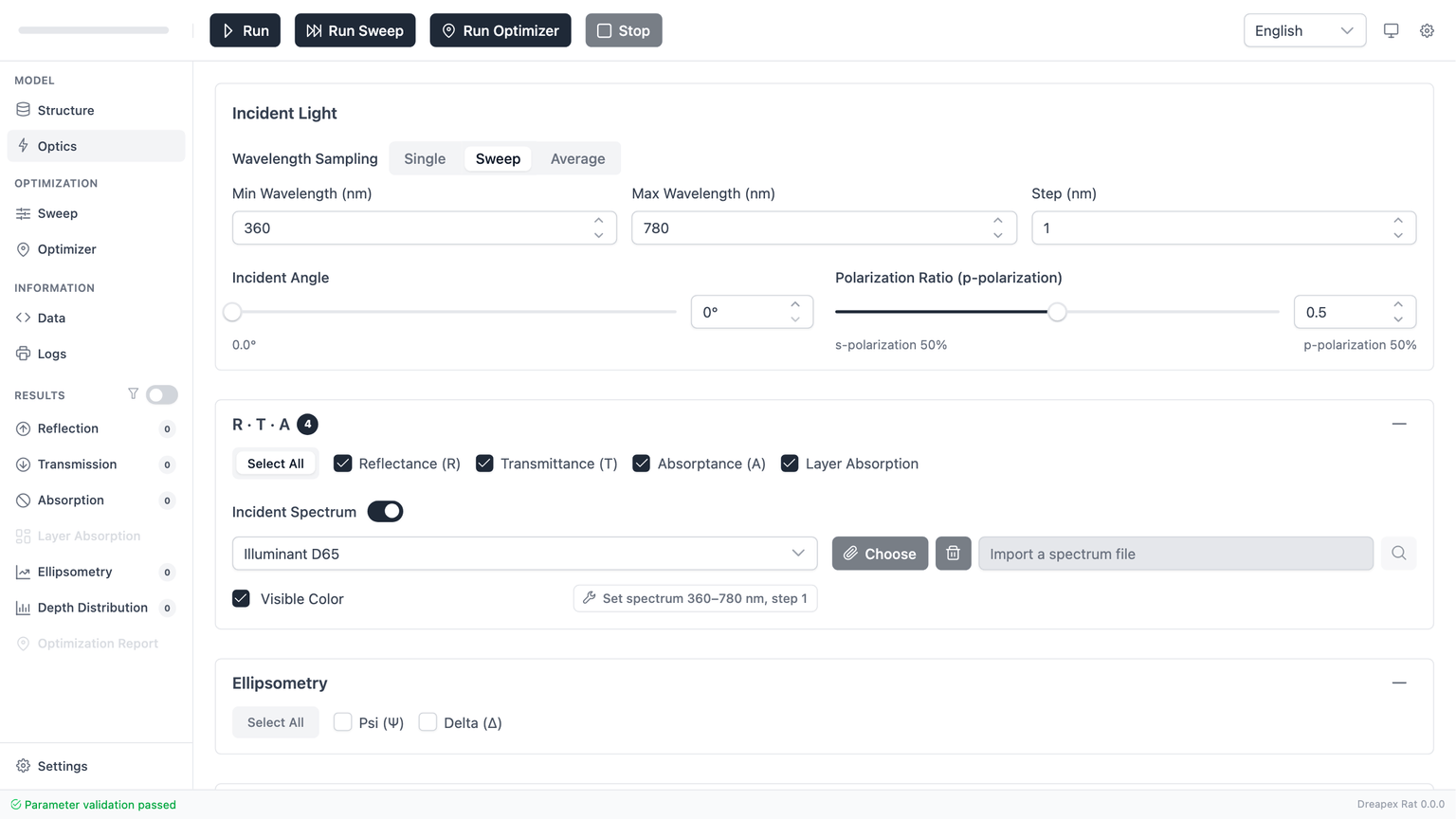
Visible Color Calculation
Enable Color Calculation enforces stricter wavelength-sampling conditions. The required settings are:
From = 360 nmTo = 780 nmStep <= 1 nm
Visible-color output therefore applies only to the visible band with sufficiently fine sampling.
The Apply Preset button writes 360 / 780 / 1 automatically. When the goal is color analysis, this preset should be used first instead of entering the values manually.
Ellipsometry and Depth Distribution
Ellipsometry and Depth Distribution are advanced result groups. Both impose stricter constraints on the wavelength mode and, in some cases, on the coherence state of the current structure.
Ellipsometry (Psi / Delta)
The Ellipsometry panel contains only Psi and Delta. These outputs are available only when the following conditions are satisfied:
| Condition | Requirement |
|---|---|
| Wavelength mode | Must not be Average |
| Structural coherence | No enabled incoherent layer may exist in the current structure |
As soon as Psi or Delta is enabled, return to Structure and confirm that every enabled layer is coherent, including top-level normal layers and enabled internal layers inside any Layer Group.
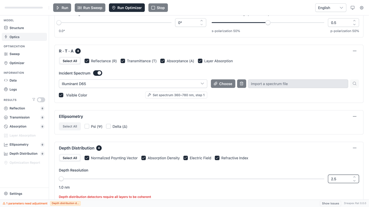
Depth-Distribution Detectors
The Depth Distribution panel contains four detectors:
| Detector | Purpose | Requires a fully coherent structure |
|---|---|---|
Poynting Vector | Power-flow distribution | Yes |
Absorption Density | Absorption-density distribution | Yes |
Electric Field | Electric-field distribution | Yes |
Refractive Index | Thickness-direction refractive-index profile | No; its structural restrictions are looser |
Two points matter:
Averagedisables the entire depth-distribution group.- Of the four detectors, the first three are the ones that truly require a fully coherent active structure.
Depth Resolution
Depth resolution becomes relevant only when at least one coherent depth detector is enabled (Poynting Vector, Absorption Density, or Electric Field).
The current rules are:
- Depth resolution must be
>= 0.1 nm. - Depth resolution must be smaller than the total thickness of the active structure.
The “total thickness” includes:
- The sum of all enabled normal-layer thicknesses.
- The sum of enabled
Layer Groupinternal thicknesses multiplied by the group repeat count.
Therefore, depth resolution is not valid merely because it is positive. For a thin active stack, a value that is too large still fails validation.
From an engineering standpoint, start with a coarse but valid depth resolution, and reduce it only when finer spatial detail is actually needed.
Dispersion Detectors
The Dispersion section provides four detectors for characterizing the phase and group-delay behavior of the thin-film stack:
| Detector | Physical quantity | Unit | Result page |
|---|---|---|---|
Phase φ(λ) | Unwrapped complex phase of the transmission/reflection coefficient | rad | Phase |
GD (Group Delay) | First derivative of phase with respect to angular frequency | fs | Group Delay |
GDD (Group Delay Dispersion) | Second derivative of phase with respect to angular frequency | fs² | GDD |
DGD (Differential Group Delay) | GD(P) - GD(S) | fs | DGD |
Prerequisites
Dispersion detectors have the strictest activation conditions on the Optics page:
| Condition | Requirement |
|---|---|
| Wavelength mode | Must be Sweep |
| Structural coherence | All enabled layers must be coherent (no incoherent layers) |
| Average mode | Incompatible; dispersion detectors are disabled in Average |
Sweep, the dispersion detector checkboxes are still visible but tagged Sweep Only and cannot be enabled. Switch to Sweep mode first.Numerical Quality
GD, GDD, and DGD are computed via numerical differentiation. The Numerical Quality setting controls the internal sampling density:
| Quality | Behavior |
|---|---|
Low | Fastest; may show noise in GDD or DGD for structures with sharp spectral features |
Medium | Default; balances speed and stability |
High | Densest grid; slowest but most stable |
Phase itself does not require differentiation and is not affected by this setting.
Sparse Output Warning
If the number of output wavelength points is below the recommended threshold, a warning appears:
| Detector | Recommended minimum wavelength points |
|---|---|
GD | 10 |
GDD | 20 |
DGD | 10 |
Increase the wavelength range or decrease the step size to obtain enough output points.
Interpolation Recommendation
When dispersion detectors are enabled, the panel may display a recommendation to change the refractive-index interpolation method from Linear to PCHIP or CubicSpline. Two convenience buttons are provided:
Use PCHIP Interpolation for Layers— sets all file-based layers to PCHIP interpolationUse CubicSpline Interpolation for Layers— sets all file-based layers to CubicSpline interpolation
Smoother interpolation reduces numerical artifacts in GD and GDD. For theory and usage details, see the Dispersion Theory chapter and the Dispersion Results chapter.
Common Conflicts and Pre-Run Checks
The most common failures on this page can be summarized as follows:
| Problem | Typical symptom | Corrective action |
|---|---|---|
Incident spectrum disappears in Single | The incident-spectrum section is no longer shown | Expected behavior; switch back to Sweep or Average for spectral weighting |
| Incident-spectrum toggle stays disabled | The user wants to enable it, but the toggle is gray | Confirm that at least one basic detector is enabled and that the mode is not Single |
| A custom spectrum imports but still fails | The file appears to load, but validation fails | Check file structure first, then verify that From / To stays inside the file coverage |
| Enabling visible color creates multiple wavelength errors | From, To, and Step all become invalid together | Use Apply Preset directly |
Psi / Delta is enabled but validation fails | The detectors can be checked, but the footer still reports an error | Return to Structure and remove every enabled incoherent layer |
| Depth resolution is positive but still invalid | The value is positive, but validation still fails | Check whether the value is greater than or equal to the active-structure thickness |
Dispersion detectors tagged Sweep Only | Checkboxes are visible but cannot be enabled | Switch wavelength mode to Sweep |
| Dispersion detectors report incoherent-layer error | Footer shows coherence validation failure | Return to Structure and make all enabled layers coherent |
| Cone angle sum exceeds limit | Validation reports incidentAngle + halfAngleDeg >= 89.9 | Reduce incident angle or cone half-angle |
Before pressing Run or moving on to the next chapter, verify the following:
- The wavelength mode matches the intended analysis.
- The wavelength inputs satisfy the current mode.
- Incident angle and
pRatioare within sensible ranges. - If cone angle is enabled,
incidentAngle + halfAngleDeg < 89.9. - At least one detector is enabled.
- If incident spectrum is enabled, the wavelength interval stays inside source coverage.
- If visible color is enabled,
360 / 780 / <= 1 nmis already satisfied. - If ellipsometry or coherent depth detectors are enabled, the structure contains no enabled incoherent layer.
- If dispersion detectors are enabled, the mode is
Sweepand all layers are coherent.
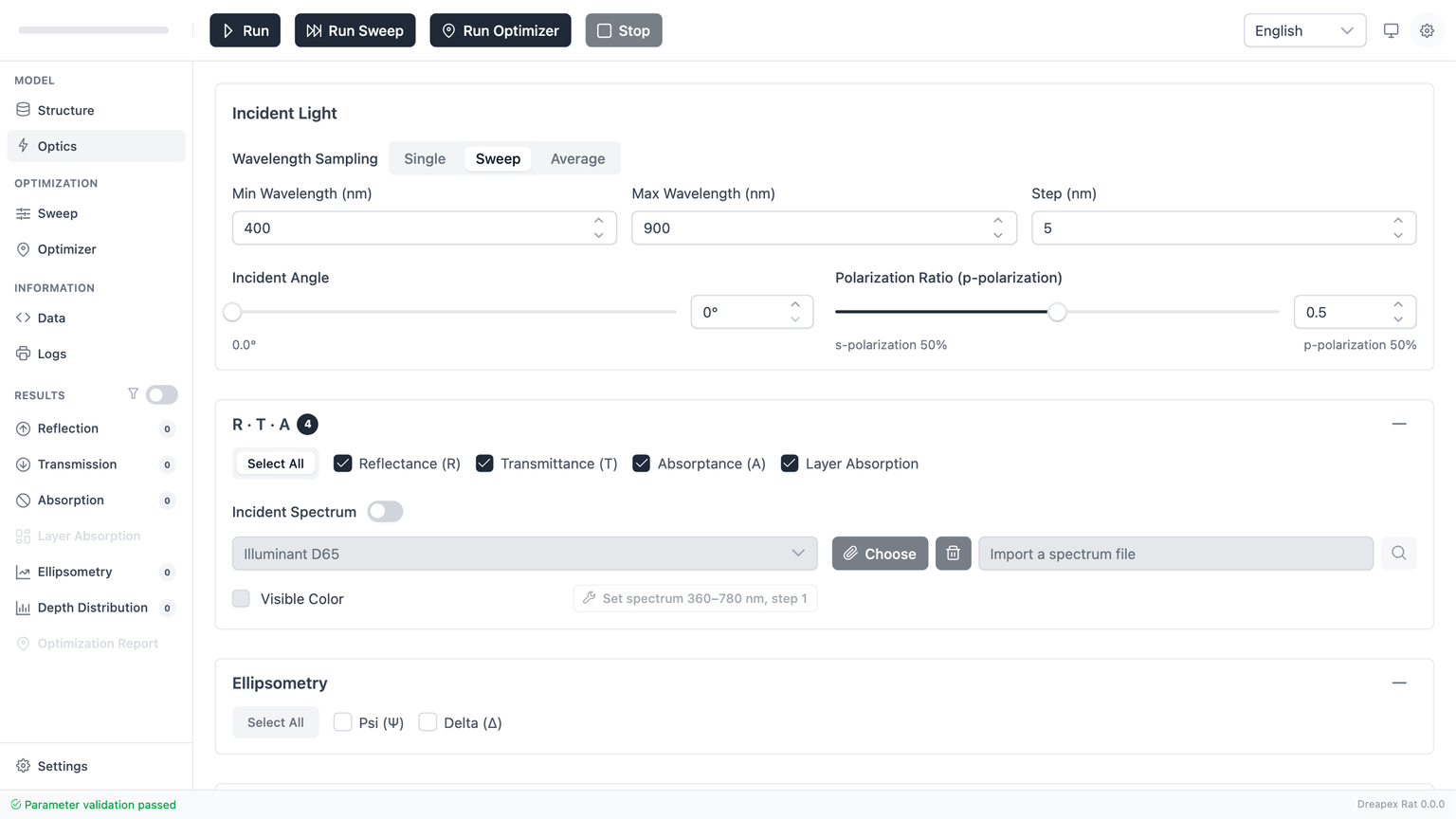
Baseline Setup Procedure
For a standard spectral calculation, use the following baseline configuration:
- Keep
Sweepmode. - Use
400 ~ 900 nmwith a5 nmstep. - Keep incident angle at
0°. - Keep
pRatio = 0.5. - Enable
R,T, andA. - Leave incident spectrum disabled.
- Run once and inspect the basic result pages first.
If the next task is visible-color analysis:
- Enable incident spectrum.
- Choose
D65or the required custom source. - Enable visible color.
- Click
Apply Preset. - Run again and inspect the spectrum and color pages.
If the next task is depth-resolved analysis:
- First confirm that
Structurecontains no enabled incoherent layer. - Select
Poynting Vector,Absorption Density, orElectric Field. - Set a valid depth resolution.
- Run again and inspect the depth-distribution outputs.
If the next task is dispersion analysis:
- Set wavelength mode to
Sweep. - Confirm that
Structurecontains no enabled incoherent layer. - Select one or more of
Phase,GD,GDD,DGD. - Set
Numerical Qualityas needed (defaultMediumis usually sufficient). - If an interpolation recommendation appears, consider applying
PCHIPorCubicSpline. - Run and inspect the Dispersion Results.
After these conditions are met, continue with the next chapter: Parameter Sweep.