Incoherent Layers
Emission Simulation Benchmark Report
2.1 Incoherent layers
The incoherent cases cover a single glass substrate, incoherent layers on either side of the emitting layer, and a structure in which every finite layer except the emitting layer is incoherent. Case (f) is a transparency control for case (c), with ZnMgO alone set to Transparent.
Incoherence describes phase correlation during propagation and does not imply zero absorption. This group includes both absorbing and transparent incoherent layers.
| Case | Configuration |
|---|---|
| (a) | Glass1 incoherent only |
| (b) | Glass1 and TFB incoherent |
| (c) | Glass1 and ZnMgO incoherent |
| (d) | Glass1, TFB and ZnMgO incoherent |
| (e) | All finite layers except QD incoherent |
| (f) | Case (c), with ZnMgO set to Transparent |
Mode comparisons use a single upper incoherent glass substrate with all other finite layers coherent. Results are presented in Chapter 1 and in the Mode section for birefringent structures.
2.1.1 Spectrum
Cases (a)–(e) compare total, s and p across the complete 560–680 nm grid in 1 nm steps and the 0–89° grid in 1° steps. Every channel has a maximum relative difference below 1 ppm. Figures show spectra at 0°; difference tables cover all wavelengths and angles.
| Case | total / ppm | s / ppm | p / ppm |
|---|---|---|---|
| (a) | 0.605019 | 0.608015 | 0.602542 |
| (b) | 0.607576 | 0.602003 | 0.589043 |
| (c) | 0.622252 | 0.611869 | 0.708272 |
| (d) | 0.614805 | 0.624769 | 0.662573 |
| (e) | 0.670343 | 0.612278 | 0.815117 |
Representative numerical values. λ = 626 nm, θ = 30°; case letters follow this section’s configuration table.
| Condition | Metric | Setfos | Dreapex TMM | Absolute difference |
|---|---|---|---|---|
| (a) · total | Spectral intensity / W·m⁻²·nm⁻¹·sr⁻¹ | 0.2608056 | 0.260805638 | 3.75e-08 |
| (b) · total | Spectral intensity / W·m⁻²·nm⁻¹·sr⁻¹ | 0.1529062 | 0.152906197 | 3.08e-09 |
| (c) · total | Spectral intensity / W·m⁻²·nm⁻¹·sr⁻¹ | 0.1039925 | 0.103992488 | 1.22e-08 |
| (d) · total | Spectral intensity / W·m⁻²·nm⁻¹·sr⁻¹ | 0.08212732 | 0.0821273276 | 7.56e-09 |
| (e) · total | Spectral intensity / W·m⁻²·nm⁻¹·sr⁻¹ | 0.08104259 | 0.0810425994 | 9.39e-09 |
| (e) · s | Spectral intensity / W·m⁻²·nm⁻¹·sr⁻¹ | 0.04125013 | 0.041250139 | 8.98e-09 |
| (e) · p | Spectral intensity / W·m⁻²·nm⁻¹·sr⁻¹ | 0.03979246 | 0.0397924604 | 4.13e-10 |
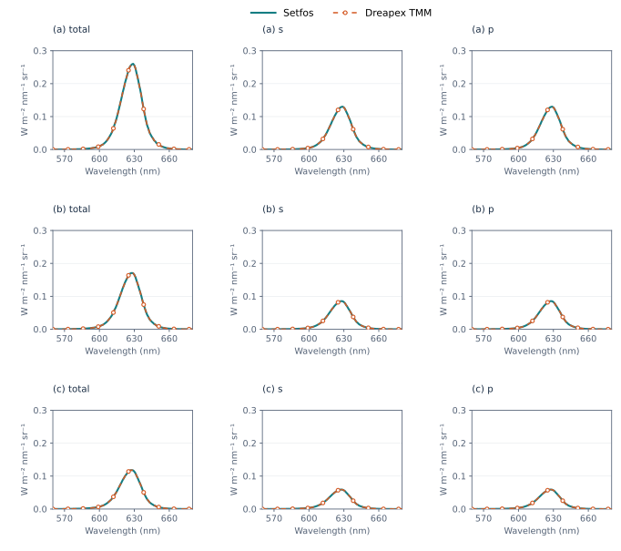
Figure 11. Incoherent layers (a), (b), (c) · Spectrum at 0° emission angle
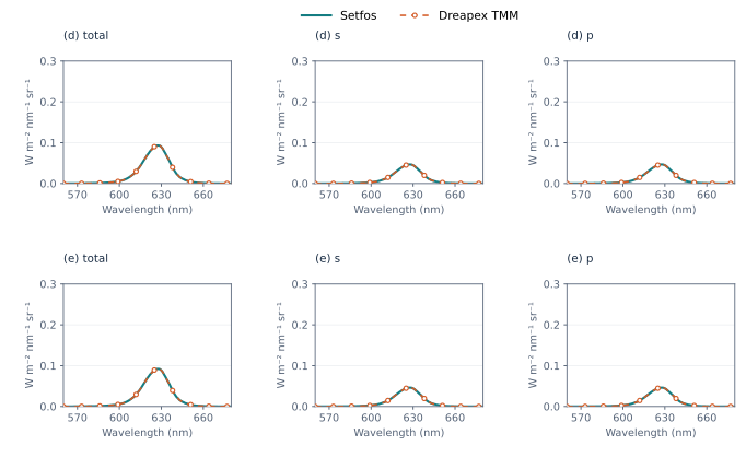
Figure 12. Incoherent layers (d), (e) · Spectrum at 0° emission angle
2.1.2 Power Dissipation
Cases (a)–(f) compare total, s and p for dissipated power, top radiation and bottom radiation, giving nine channels. Wavelengths span 560–680 nm in 10 nm steps; effective index n_eff spans 0–4 in steps of 0.01. All channels have very small differences < 1 ppm outside registered critical points. Figures use the 610 nm slice.
Bottom radiation is zero under the absorbing conditions in cases (c), (d) and (e), and nonzero in the transparency control (f). Both outcomes agree with the reference. This distinction concerns the reported radiation component and does not imply that no energy enters an adjacent absorbing material.
| Case | Assessment | total / ppm | s / ppm | p / ppm |
|---|---|---|---|---|
| (a) | Dissipated power | 0.114682 | 0.114682 | 0.114682 |
| (a) | Top radiation | 0.114682 | 0.114682 | 0.114682 |
| (a) | Bottom radiation | 0.114682 | 0.114682 | 0.114682 |
| (b) | Dissipated power | 0.114683 | 0.114686 | 0.114683 |
| (b) | Top radiation | 0.114684 | 0.114684 | 0.114684 |
| (b) | Bottom radiation | 0.114682 | 0.114682 | 0.114682 |
| (c) | Dissipated power | 0.114682 | 0.114683 | 0.114682 |
| (c) | Top radiation | 0.114682 | 0.114682 | 0.114682 |
| (c) | Bottom radiation | — | — | — |
| (d) | Dissipated power | 0.114702 | 0.114706 | 0.114701 |
| (d) | Top radiation | 0.114684 | 0.114684 | 0.114684 |
| (d) | Bottom radiation | — | — | — |
| (e) | Dissipated power | 0.114702 | 0.114706 | 0.114701 |
| (e) | Top radiation | 0.114684 | 0.114684 | 0.114684 |
| (e) | Bottom radiation | — | — | — |
| (f) | Dissipated power | 0.114682 | 0.114683 | 0.114682 |
| (f) | Top radiation | 0.114682 | 0.114682 | 0.114682 |
| (f) | Bottom radiation | 0.114682 | 0.114682 | 0.114682 |
Values are maximum relative differences in ppm. “—” denotes an all-zero reference with exactly zero absolute difference.
Representative numerical values. λ = 610 nm, n_eff = 0.50; total component.
| Condition | Metric | Setfos | Dreapex TMM | Absolute difference |
|---|---|---|---|---|
| (a) | Top radiation / W·m⁻²·nm⁻¹ | 0.391561369 | 0.391561414 | 4.49e-08 |
| (a) | Bottom radiation / W·m⁻²·nm⁻¹ | 8.58142959e-05 | 8.58143058e-05 | 9.84e-12 |
| (c) | Top radiation / W·m⁻²·nm⁻¹ | 0.0722704314 | 0.0722704397 | 8.29e-09 |
| (c) | Bottom radiation / W·m⁻²·nm⁻¹ | 0 | 0 | 0 |
| (e) | Top radiation / W·m⁻²·nm⁻¹ | 0.0794515741 | 0.0794515832 | 9.11e-09 |
| (e) | Bottom radiation / W·m⁻²·nm⁻¹ | 0 | 0 | 0 |
| (f) | Top radiation / W·m⁻²·nm⁻¹ | 0.0722658387 | 0.072265847 | 8.29e-09 |
| (f) | Bottom radiation / W·m⁻²·nm⁻¹ | 0.118077637 | 0.118077651 | 1.35e-08 |
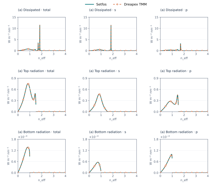
Figure 13. Incoherent layers (a) · Power Dissipation at 610 nm
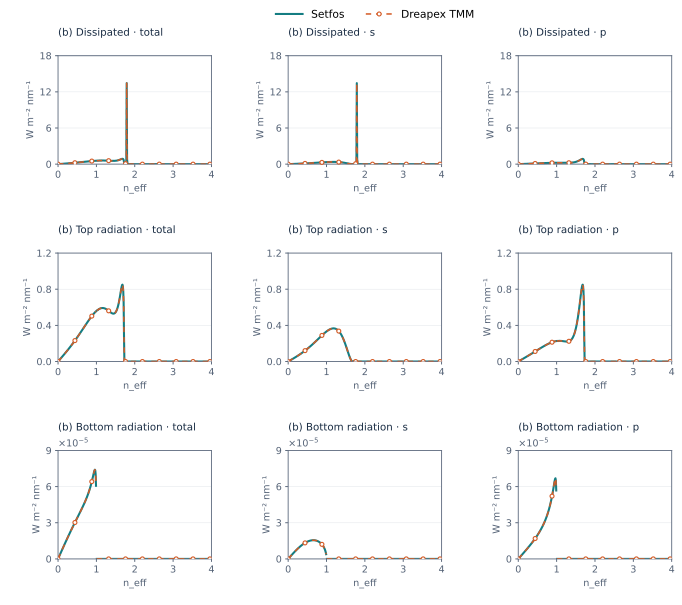
Figure 14. Incoherent layers (b) · Power Dissipation at 610 nm
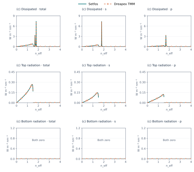
Figure 15. Incoherent layers (c) · Power Dissipation at 610 nm
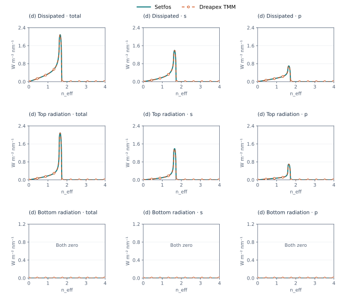
Figure 16. Incoherent layers (d) · Power Dissipation at 610 nm
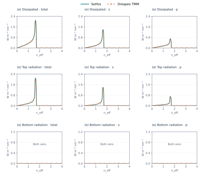
Figure 17. Incoherent layers (e) · Power Dissipation at 610 nm
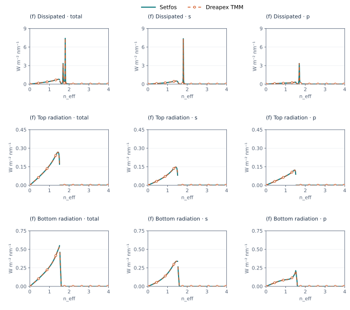
Figure 18. Incoherent layers (f) · Power Dissipation at 610 nm