Mode & Emission
This guide introduces the Mode and Emission results, which show how emission power is divided among outcoupling, substrate, waveguide, absorption, and nonradiative channels, together with the Purcell factor, effective quantum efficiency, and lifetime. Use them to analyze device loss paths and emission efficiency.
Mode.Mode fractions
The Mode page decomposes the normalized exciton budget into 7 channels:
| Channel (UI label) | Abbreviation | Physical meaning |
|---|---|---|
| Top Outcoupling | TOC | Light exiting from the top into the environment medium |
| Bottom Outcoupling | BOC | Light exiting from the bottom into the environment medium |
| Substrate | SUB | Light confined in the substrate by total internal reflection at the substrate–air interface |
| Waveguide | WVG | Light trapped in the organic stack by total internal reflection and interference |
| Evanescent | EVA | Energy dissipated as evanescent waves, generally SPP loss |
| Absorption | ABS | Power absorbed along the TOC, SUB, and BOC propagation paths before escape |
| Non-radiative | NRA | Intrinsic non-radiative decay of the emitter (appears when Quantum Efficiency < 1) |
The k_in integration intervals, ABS/BOC assignment, and TOC/LEE/EQE/NRA relationships are given in Power Dissipation and Optical Modes. The currently supported structures and refractive-index conditions are defined in the Emission Detectors guide.
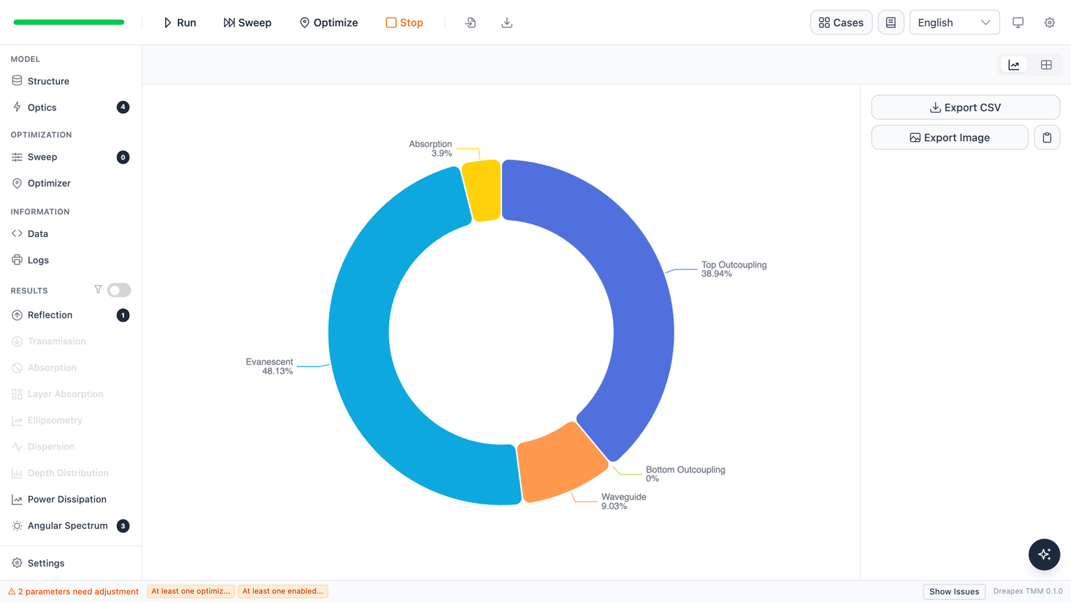
Single / Weighted Average: donut chart
When the Wavelength Mode is Single or Weighted Average, the Mode page displays a donut chart showing the power fraction of all 7 channels at a single effective wavelength. The legend lists each channel name and its percentage.
Sweep mode: stacked area / line chart
When Wavelength Mode is Sweep, the x-axis becomes wavelength (nm) and the y-axis shows per-channel fraction. The default is a Stacked Area chart — the 7 channels sum to approximately 1 across the wavelength range, making it easy to see how each channel evolves with wavelength. Switch to the Line chart type to inspect individual channels without overlap.
Not-converged marker (*)
When one or more modes at a given wavelength fail to converge, the wavelength label is appended with *. A legend hint reads: * marks wavelengths with one or more modes that failed to converge.
Non-convergence typically occurs when the numerical tolerance is too loose or when the structure contains a very strong SPP resonance. Reduce the Tolerance value in the Mode detector configuration on the Optics page and re-run.
Sweep vs Weighted Average
In Sweep mode, the Mode page outputs a separate set of 7 channel fractions for each wavelength point, with the x-axis spanning the full wavelength range.
In Weighted Average mode, the wavelength dimension collapses to a single weighted value and the Mode page reverts to the donut chart display, behaving the same as Single mode.
Weighted Average first calculates a photon-number-spectrum-weighted Purcell factor for each emitter:
Here, is the full-spectrum Purcell factor of emitter , indexes wavelength samples, and is the wavelength at sample . is that emitter's photon-number spectral weight at the sample, and is its single-wavelength Purcell factor. Effective quantum efficiency, lifetime, and full-spectrum channel fractions use the same and photon-number weighting convention.
Mode results from several emitters use normalized mixing weights:
Here, is the mixing weight of emitter , is its Multiplication Factor, and is its Conversion Efficiency; index runs over all enabled emitters. is the combined fraction of optical channel , is the emitter's effective quantum efficiency in the selected wavelength mode, and is the conditional fraction of its radiated photons entering channel . is the combined non-radiative fraction. All optical-channel fractions plus sum to 1.
Non-radiative channel (NRA) represents non-radiative decay after exciton formation. For one emitter, ; it is not and does not include conversion loss . Changing Conversion Efficiency for one emitter does not alter its relative Mode composition. With several emitters, different values change the combined result through .
Emission (Purcell / effective QE)
The Emission view extracts the following per-emitter properties from the Mode detector results:
| Property (UI label) | Physical meaning |
|---|---|
| Purcell Factor | Enhancement factor F for spontaneous emission rate by the optical environment |
| Decay Rate Enhancement | Ratio of environment-modified to intrinsic total decay rate, b/b₀ |
| Quantum Eff. (Intrinsic) | Input intrinsic quantum efficiency q₀ (not affected by Purcell) |
| Quantum Eff. | Purcell-corrected effective quantum efficiency q_eff |
| Lifetime (Intrinsic) | Input intrinsic total-decay lifetime τ₀ |
| Lifetime | Purcell-corrected effective lifetime τ |
Formulas for effective quantum efficiency and lifetime are given in Purcell Effect.
Single / Weighted Average mode
When Wavelength Mode is Single or Weighted Average, each emitter is shown as a description card listing all properties (both intrinsic and effective values). There is no chart and no view toggle.
Sweep mode
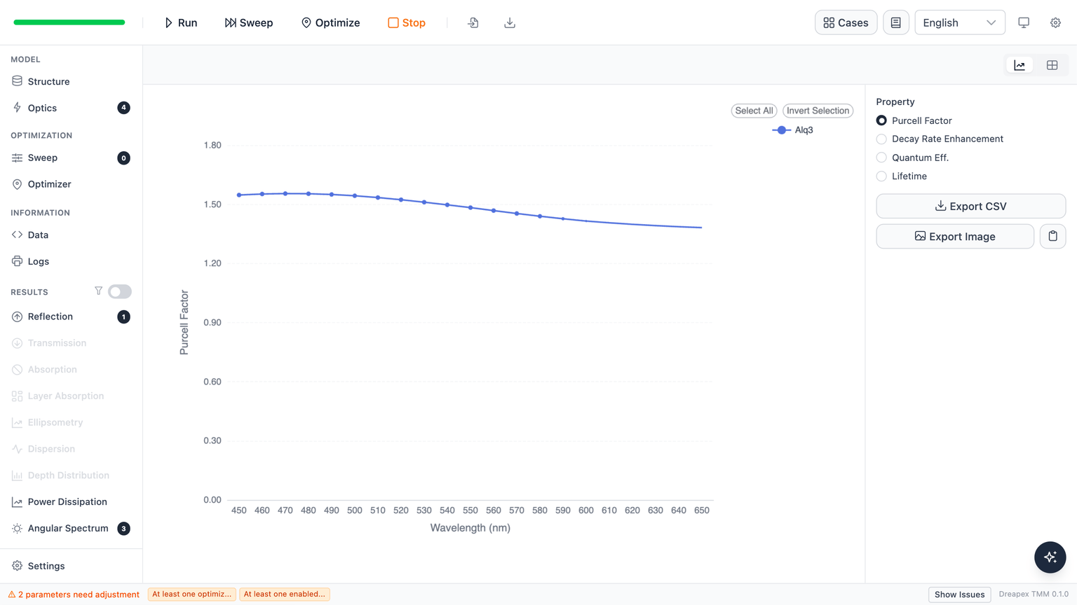
When Wavelength Mode is Sweep (≥ 2 wavelength points), the page switches to chart/table mode. The right sidebar displays:
- Property: a RadioButton group to select Purcell Factor / Decay Rate Enhancement / Quantum Eff. / Lifetime
- Emitter: a dropdown showing all emitter names; selecting
All emittersplots one line per emitter
The x-axis is wavelength (nm); the y-axis is the selected property. The Purcell Factor typically shows a peak at wavelengths coinciding with microcavity resonances.
Controls
The common chart/table toggle and export controls (Export CSV, Export Image, Copy Image) are described in Basic Optical Results. Page-specific controls:
| Control | Function |
|---|---|
| Chart type selector | Stacked Area / Line (Mode sweep mode only) |
| Property (RadioButton) | Select which physical quantity to display in the Emission view (Sweep mode only) |
| Emitter selector | Select a single emitter or all emitters (Sweep mode only) |
If the page shows "No data", the most common causes are:
- no calculation has been run yet
- no layer is marked as emissive (enable the
Emis.toggle in the Structure page) - the Mode detector is not checked in the Emission detector lane of the Optics page (Emission view also depends on this)
Next
- Understand the k_in integration boundaries for all 7 channels: Power Dissipation and Optical Modes
- Understand the Purcell-factor derivation and effective-QE formula: Purcell Effect
- Observe how mode fractions and Purcell Factor change across a parameter sweep: Swept Emission