Emission Detectors
This guide explains how to enable the Power Dissipation, Intensity, and Mode emission detectors in Optics and what each one produces. Afterward, you can choose detectors for your analysis goal.
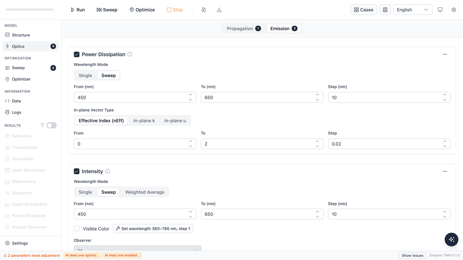
The Emission lane
The Emission lane provides three detectors:
| Detector | Output |
|---|---|
| Power Dissipation | Emitter dipole power coupled into in-plane wavevectors (power dissipation spectrum). Results: Power Dissipation. |
| Intensity | Far-field emission intensity vs. wavelength (and optionally angle). Results: Intensity. |
| Mode | Guided and leaky optical modes supported by the emissive structure. Results: Mode. |
Structure support
Material and single-layer limits
| Layer role | Incoherent | Birefringent | Absorbing | Additional rule |
|---|---|---|---|---|
| Regular layer | ✅ | ✅ | ✅ | Incoherence and birefringence cannot be enabled together |
| Emissive layer (EML) | ❌ | ✅ | ❌ | With Transparent enabled, extinction coefficients are set to 0; with it disabled, validation passes only when they are already 0 |
| Top Medium | — | ❌ | ❌ | — |
| Bottom Medium | — | ❌ | ✅ | — |
“Birefringent” in this table means uniaxial birefringence with the optical axis normal to the film plane. Tilted or arbitrary optical axes and biaxial materials are not supported. Top Medium and Bottom Medium do not use the coherent/incoherent setting, so that column is marked “—”.
Detector support by structure
The table below assumes every layer already satisfies the material and single-layer limits above. “First structure layer” means the first finite-thickness film after Top Medium.
| Structure scenario | Power Dissipation | Intensity | Mode |
|---|---|---|---|
| One EML and all structure layers coherent | ✅ | ✅ | ✅ Conditional* |
| Multiple EMLs and all structure layers coherent | ✅ | ✅ | ✅ Conditional* |
| The first structure layer is the only incoherent layer | ✅ | ✅ | ✅ Conditional* |
| An incoherent layer is not the first structure layer | ✅ | ✅ | ❌ |
| More than one incoherent layer is present | ✅ | ✅ | ❌ |
| EMLs are separated by an incoherent layer | ✅ | ✅ | ❌ |
* Mode conditions:
- With no top incoherent layer:
- When the first structure layer is the only incoherent layer:
- When Bottom Medium is transparent:
- When Bottom Medium is absorbing, calculation is allowed, but BOC is
0. - With multiple EMLs, every EML must satisfy the applicable conditions above.
Here, is the Top Medium index, is the index of the incoherent first structure layer, is the Bottom Medium index, and is the EML ordinary index.
Wavelength modes
Available wavelength modes per detector:
| Detector | Single | Sweep | Weighted Average |
|---|---|---|---|
| Power Dissipation | Yes | Yes | No |
| Intensity | Yes | Yes | Yes |
| Mode | Yes | Yes | Yes |
Power Dissipation has no Weighted Average mode. The option is not available for that detector. For spectrally weighted emission power information, use the Intensity detector in Weighted Average mode instead.
Mode behavior:
- Single: Calculates at one specified wavelength; result is a one-dimensional distribution (in-plane vector or angle as the x-axis).
- Sweep: Calculates at each wavelength from
FromtoToinStepincrements; result includes the full spectral dimension, with heatmap and line-chart display options. - Weighted Average (Intensity / Mode only): Collapses the wavelength dimension to one effective result. Intensity uses radiant-power spectral weights, while Mode uses photon-number spectral weights. Both are derived from the emitter's Spectrum Unit, making the mode useful for comparing full-spectrum intensity or outcoupling behavior across structures.
At a fixed wavelength, Mode depends on the structure, refractive indices, dipole position, orientation, and other optical conditions—not on the spectrum amplitude. Spectrum unit and lineshape enter Mode only when wavelengths are combined in Weighted Average.
Probability and Power should produce the same Weighted Average when converted with . Here, is the photon energy, is the Planck constant, is the speed of light in vacuum, and is wavelength.Per-detector configuration
Power Dissipation
In addition to wavelength parameters, Power Dissipation requires an In-plane Vector Type to define the x-axis physical quantity:
| Option | Label | Default range |
|---|---|---|
nEff | Effective Index (nEff) | 0 → 2.0, step 0.01 |
In-plane k | In-plane k | 0 → 1, step 0.01 |
In-plane u | In-plane u | 0 → 1, step 0.01 |
The default is nEff (effective refractive index).
Intensity
In addition to wavelength parameters, Intensity has an Angle Mode:
| Option | Description |
|---|---|
| Single | Samples far-field intensity at one specified angle only. |
| Sweep | Samples across an angle range from From to To at Step intervals. Default: 0°–80°, step 5°. |
Angle constraints: 0° ≤ angle ≤ 90°; Sweep mode requires angleTo > angleFrom.
Mode
In addition to wavelength parameters, Mode has a Tolerance field:
- Default:
1e-4 - Controls mode-search convergence precision; must be greater than 0.
- Wavelengths with unconverged modes are marked with
*in the results.
Intensity Color
Intensity Color is a derived feature of the Intensity detector that computes CIE chromaticity coordinates and visible emission color.
- Intensity detector is enabled
- Wavelength Mode is Sweep (not Single or Weighted Average)
- The sweep covers 360–780 nm at step ≤ 5 nm
When Wavelength Mode is not Sweep, the Visible Color toggle is disabled and shows the tooltip:
Visible Color can only be enabled when Wavelength Mode is Sweep.
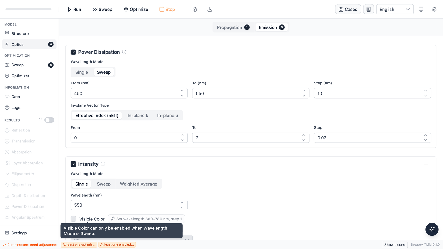
If the current configuration does not meet the requirements, a hint is shown alongside an auto-fix button: clicking it enables the Intensity detector and sets the wavelength sweep to 360–780 nm at step 1 nm in a single action.
Color calculation allows a step up to 5 nm, but use 1 nm for color comparison. When the actual result spacing is greater than 1 nm, the Intensity Color page shows a nonblocking coarse-sampling note. Narrow emission peaks with FWHM below about 10 nm are especially sensitive to grid placement.
Color output also requires selecting a chromaticity observer:
- 2° (default)
- 10°
CCT and Duv are available only with the 2° observer. The 10° observer uses the CIE 1964 chromaticity locus and omits those two metrics. See Intensity Color for per-angle metrics and baseline comparison.
Detector guards
When the structure has no emissive layer (EML):
- An info banner is shown at the top of the Emission lane: "No emissive layer (EML) in the structure. Mark a layer as emissive on the Structure page to enable Emission detectors."
- Emission detector cards are not disabled — users can still freely check or uncheck detectors. Cards are only locked while a calculation is in progress.
Next
- Configure sweep parameters: Parameter Sweep
- View simulation results: Power Dissipation · Intensity · Intensity Color · Mode