Intensity
This guide introduces the spectrum, angular-distribution, global-peak, envelope-FWHM, and normalized views in Intensity. These views show the far-field intensity of a light-emitting device and reduce each complete spectrum to scalar results that are convenient for scan comparisons.
Spectral weight and source strength
The far-field contribution of one emitter can be summarized as
Here, is the intensity contribution of emitter at output angle and wavelength . is its Multiplication Factor, is its Conversion Efficiency, is its radiant-power spectral weight, and is the far-field response determined by the structure, dipole position, and orientation.
With Spectrum Unit set to Probability, the input photon-number spectrum is converted to power using the photon-energy factor . With Power, the input values are used directly as . Here, is the Planck constant and is the speed of light in vacuum. For one emitter, and scale raw intensity linearly but do not change a normalized spectrum or normalized angular distribution. With several emitters, different weights can change the combined spectrum, angular distribution, and color.
Example Setup
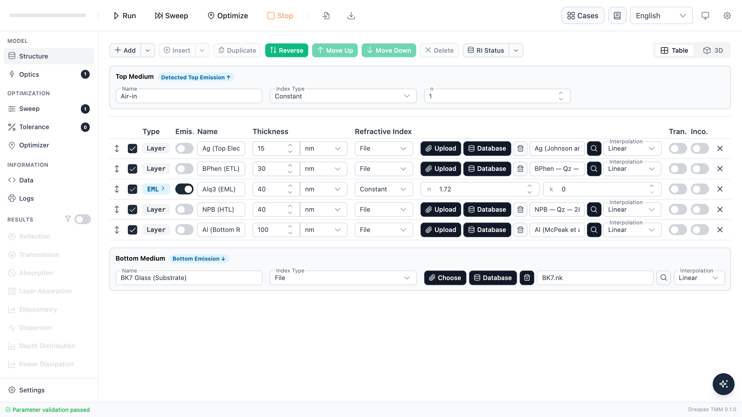
The example is a green top-emitting OLED: Air / Ag / BPhen / Alq₃ EML / NPB / Al / BK7. Ag and Al use measured dispersion from the refractive-index database. BPhen and NPB use quartz-substrate variants from the Aulika OLED material database. No matching Alq₃ entry is available, so the EML retains a constant refractive index and uses a generated emission spectrum that covers the complete calculation band.
| Item | Example value |
|---|---|
| Top / bottom medium | Air / BK7 Glass |
| Layer stack | Ag 15 nm / BPhen 30 nm / Alq₃ 40 nm / NPB 40 nm / Al 100 nm |
| Database materials | Ag (Johnson and Christy 1972), BPhen (Qz, 82 nm), NPB (Qz, 287 nm), Al (McPeak et al. 2015) |
| Emitter | Alq₃ with a generated broadband spectrum peaking near 530 nm |
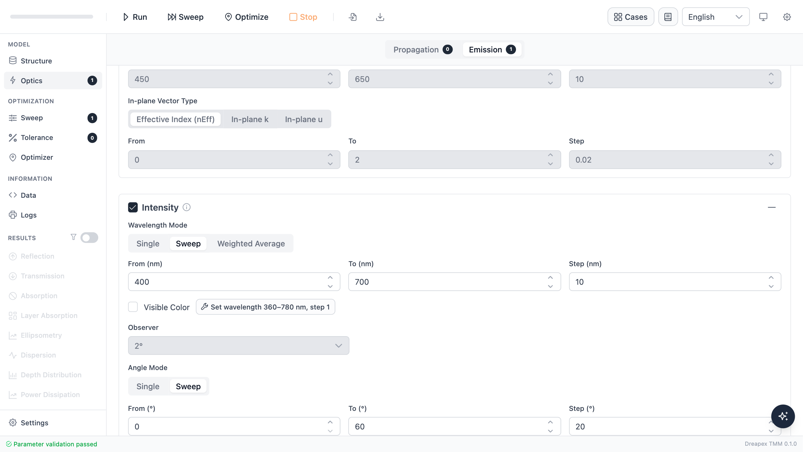
| Intensity wavelength | 400–700 nm, 10 nm step |
| Output angle | 0–60°, 20° step |
Spectrum
When Wavelength Mode is set to Sweep, the Intensity page shows far-field emission intensity (a.u.) vs. wavelength (nm) for each polarization channel.
Polarization: switch between TE / TM / Total using the polarization SelectButton. All three curves can be shown simultaneously, or a single curve selected through the legend.
Chart type: when only the wavelength dimension is present (Angle Mode = Single or Weighted Average), the default is a line chart. When an angle sweep is also active (Angle Mode = Sweep), the chart can be toggled between line and heatmap, and the x-axis can be switched between Wavelength and Angle.
Single-value mode (angle = Single and wavelength = Single or Weighted Average): the chart area is hidden and the page switches to table-only mode.
Spectrum Peaks and Envelope FWHM
Sweep with at least two wavelength samples, the Results area provides three derived views. They read only the raw Intensity spectrum; normalized spectra, single-wavelength results, and Weighted Average results are not used as sources.For each spectrum identified by “scan combination × output angle × polarization,” define
Here, is the Global Peak Intensity, Peak Wavelength is the wavelength of the unique highest raw sample, is the half-maximum level, and are the outermost half-maximum crossings, and is Envelope FWHM in nm.
| Metric | Definition |
|---|---|
| Global Peak Intensity | The largest sampled value in the complete raw spectrum |
| Global Peak Wavelength | The wavelength of the unique global-maximum sample; there is no peak-top fit and no local-peak tracking |
| Envelope FWHM | The outermost wavelength span occupied by all regions at or above half maximum |
Half maximum is taken directly from the current y-values. There is no power/amplitude conversion, baseline subtraction, or smoothing. Crossings are linearly interpolated between neighboring samples, including on nonuniform wavelength grids. Total, TE, and TM are evaluated independently.
Data Status Interpretation
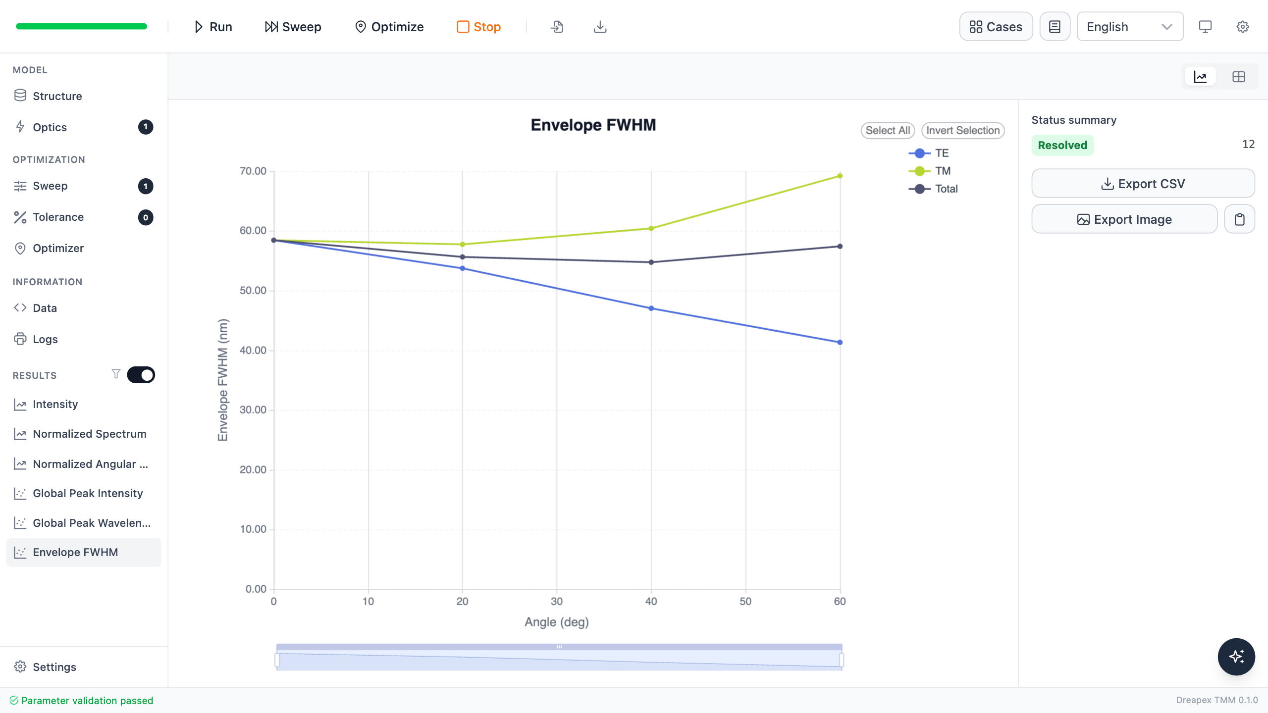
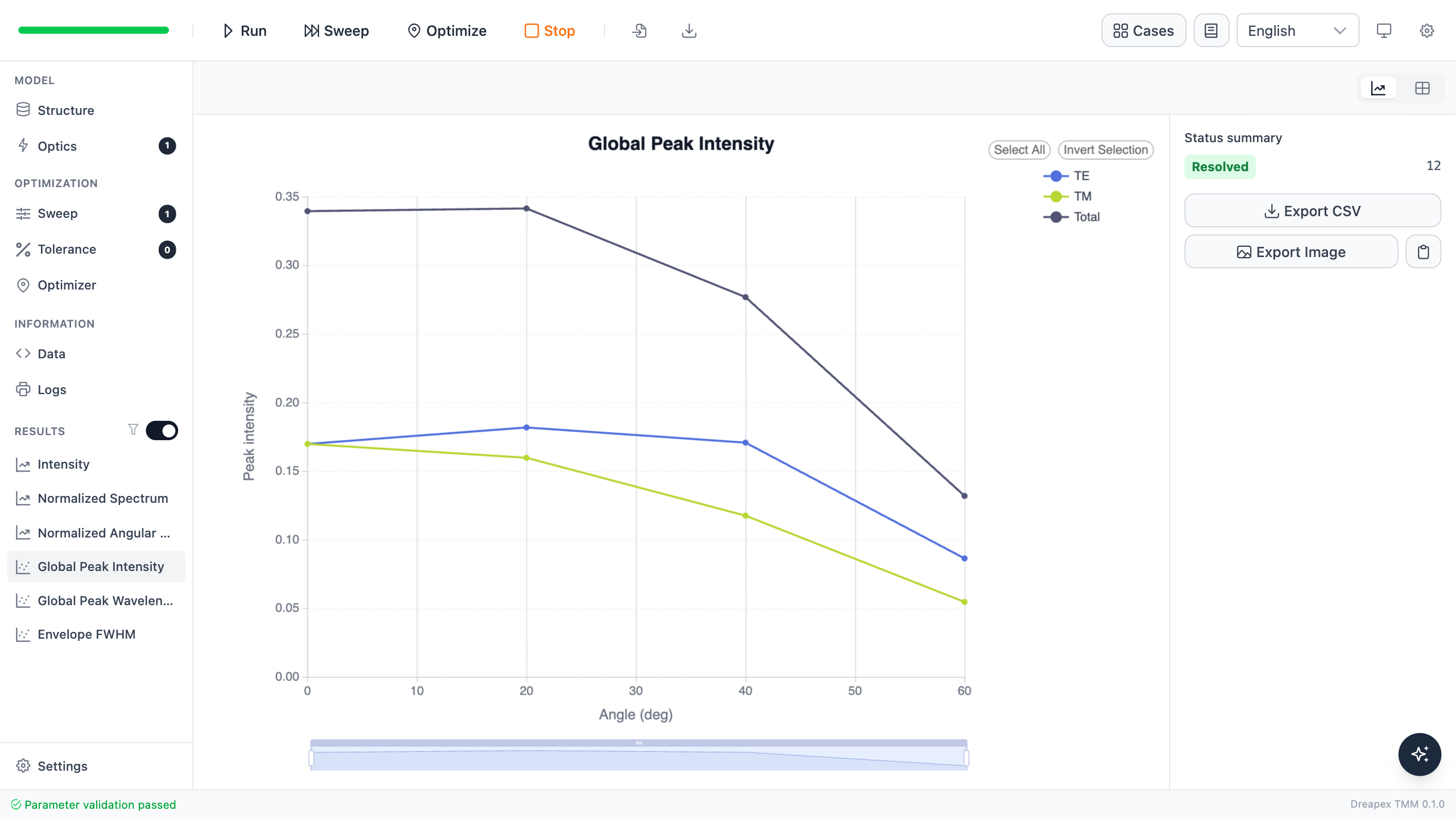
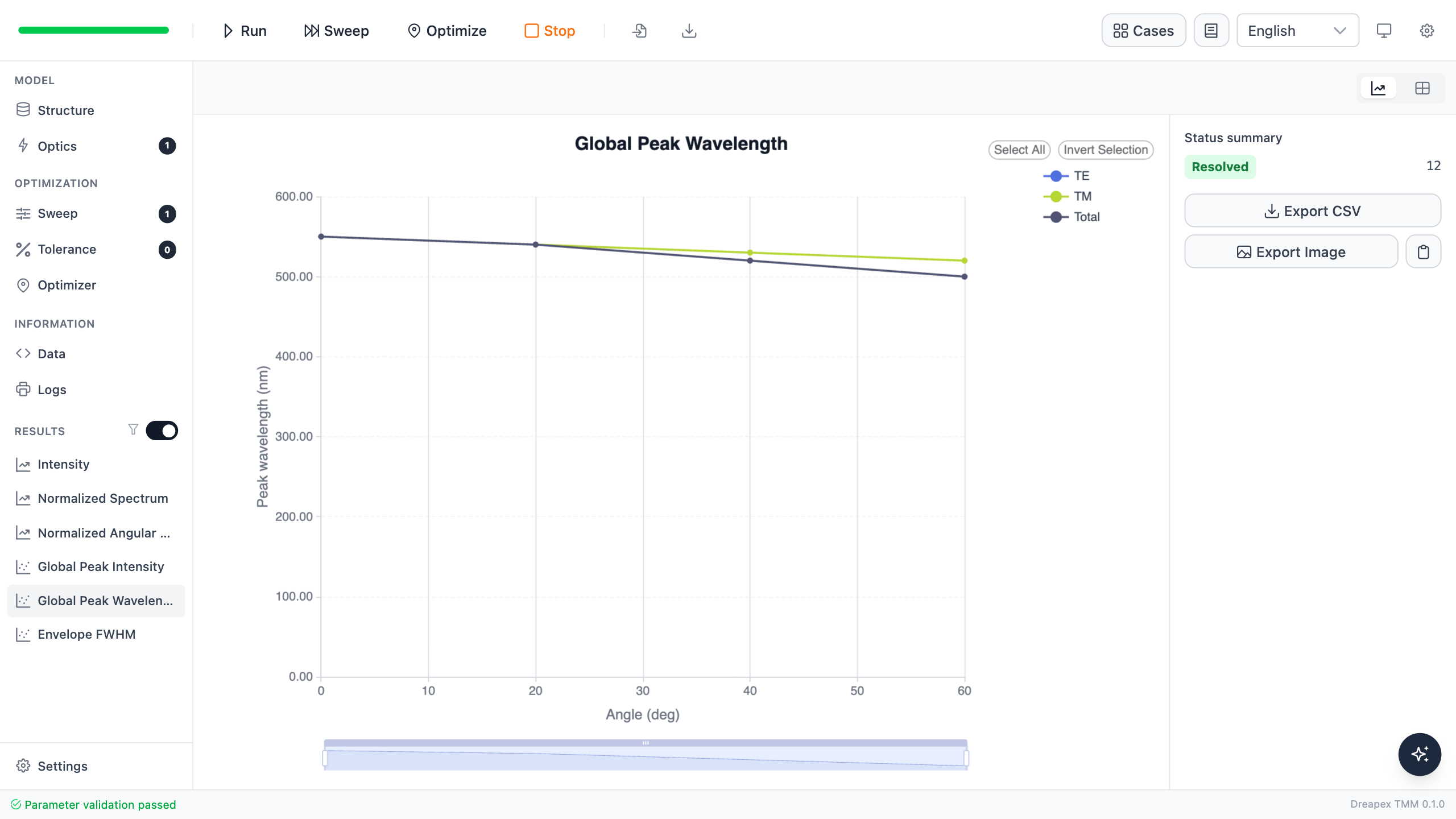
Data statuses appear in two places: Status summary in the chart sidebar counts each status, while the DataTable status column classifies every spectrum. The green Resolved 12 in Figure 4 means that all 12 spectra from four angles and three polarizations have complete FWHM values.
In a DataTable, first check whether the metric cell contains a value, then read the status in the same row. A blank means that the current spectrum cannot determine the metric completely; it does not mean zero. “Multiple half-max regions” retains an FWHM value, but that value is the outer span of the complete multipeak envelope.
The six panels in Figure 5 correspond to the six table rows from left to right and top to bottom.
- Blue curve: the raw intensity spectrum.
- Blue dots: samples at the global maximum. Multiple blue dots leave Peak Wavelength blank.
- Orange dashed line: half of the global peak value.
- Bright-green dots: valid crossings of the spectrum and the half-maximum line. The two outermost crossings determine Envelope FWHM.
- Red marks: a sampling boundary or data gap prevents complete crossings, so FWHM is blank.
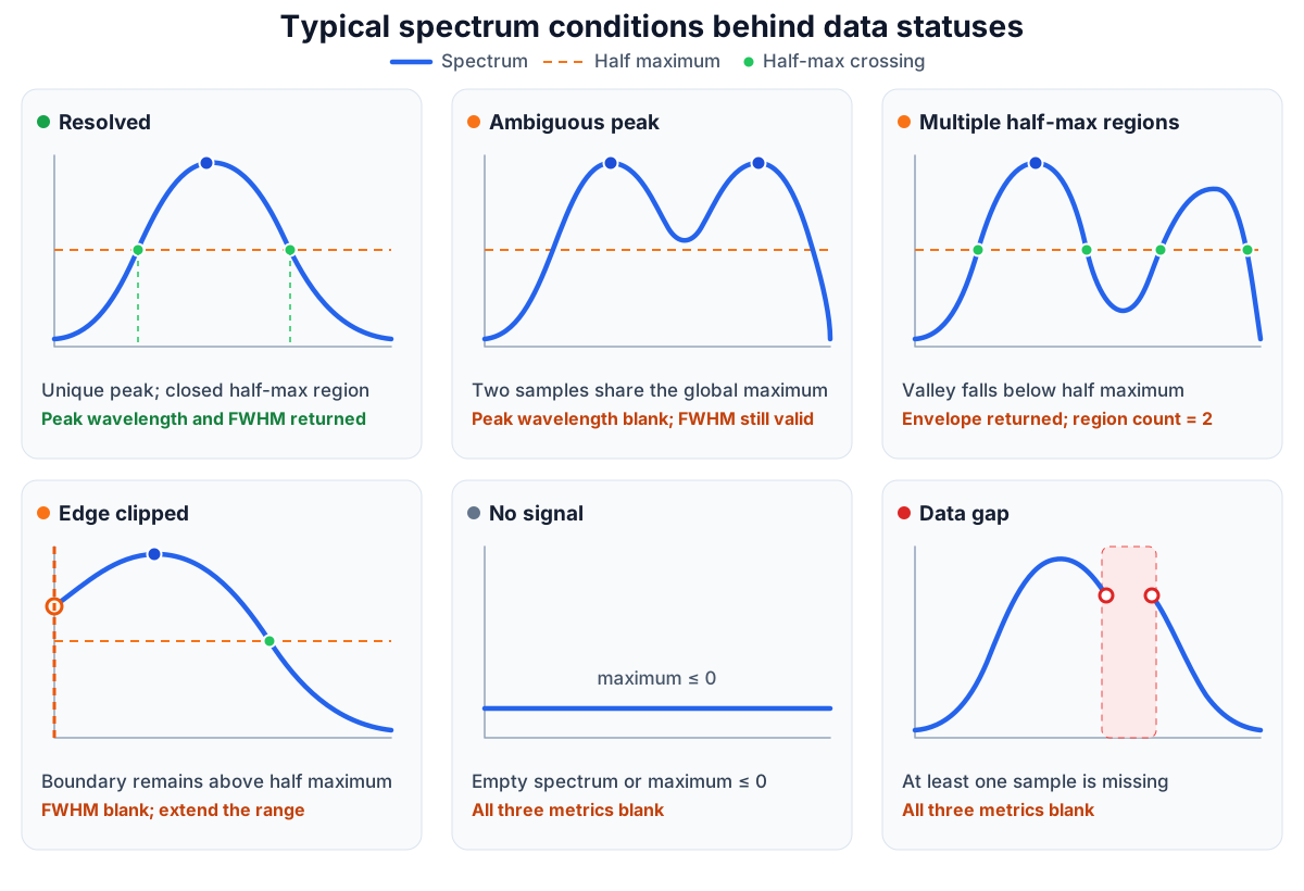
| UI status | Value result | Corresponding spectrum and action |
|---|---|---|
| Resolved | The corresponding metric is available | One highest point and a half-max region closed inside the wavelength range; compare directly |
| Ambiguous peak | Peak Intensity remains; Peak Wavelength is blank; FWHM is evaluated independently | Two or more samples equal the global maximum; inspect a plateau or equal peaks |
| Multiple half-max regions | Envelope FWHM and the region count remain available | A valley falls below half maximum; interpret the value as the outer span of the complete multipeak envelope |
| Edge clipped | FWHM is blank; Peak is evaluated independently | A wavelength boundary remains above half maximum; extend the wavelength range |
| No signal | All three metrics are blank | The spectrum is empty or its maximum is not positive; check source strength, the Intensity detector, and the structure |
| Data gap | All three metrics are blank | At least one wavelength sample is missing; repair the data and run again |
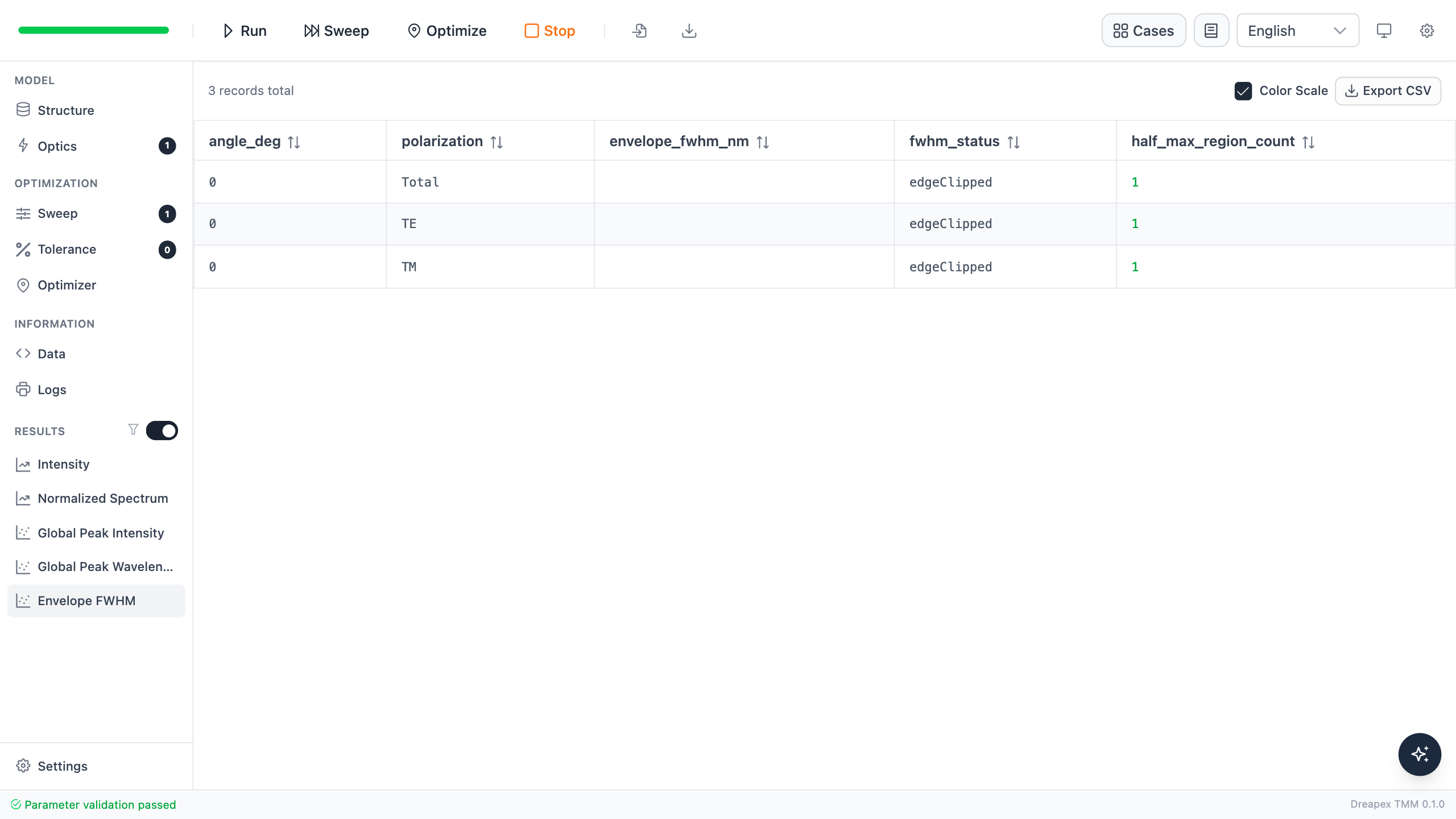
Figure 6 is the real DataTable counterpart of “Edge clipped” in the lower-left panel of Figure 5. The example narrows the wavelength range to 520–540 nm, so the curve remains above half maximum at the boundary. The FWHM cell is therefore blank, the status is edgeClipped, and the half-max region count remains 1.
- Boundary sample exactly equal to half maximum: the sample is a valid crossing and FWHM is returned normally.
- Multiple half-max regions together with edge clipping: FWHM is blank and the status is “Edge clipped,” while the region count remains available. Extend the wavelength range and run again.
- Peak Wavelength marked “Ambiguous peak”: only Peak Wavelength is blank. Peak Intensity remains available and FWHM is evaluated independently.
A multipeak spectrum still produces one set of global metrics: at most one Global Peak Intensity, one Global Peak Wavelength, and one Envelope FWHM for each spectrum and polarization.
- If several peaks remain connected above half maximum, Envelope FWHM is the distance between the two crossings of that region.
- If a valley falls below half maximum and creates several regions, Envelope FWHM is the distance from the leftmost to the rightmost crossing and is marked “Multiple half-max regions.”
- If several samples equal the global maximum, Peak Intensity remains, Peak Wavelength is blank, and FWHM is evaluated independently.
- If the unique highest sample is at a wavelength boundary, its sampled-domain Peak Wavelength remains valid.
Charts across scans
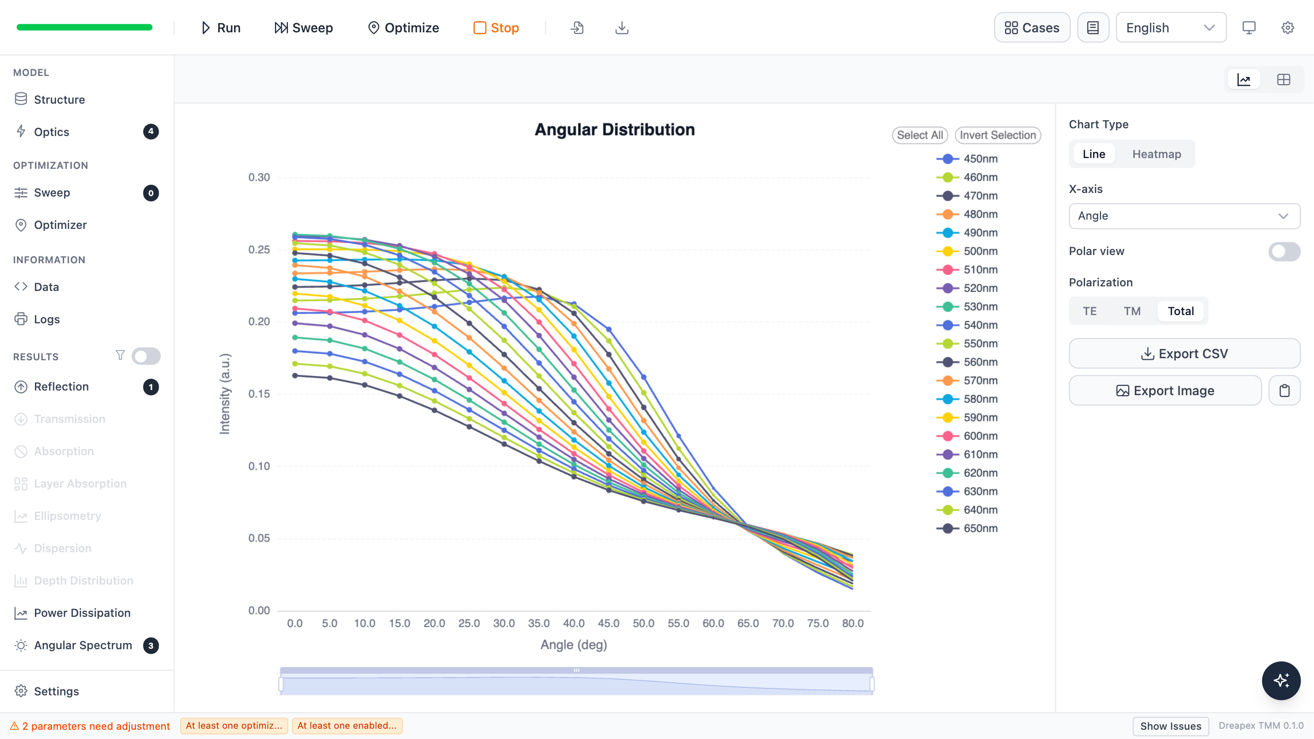
The real result below uses Angle Sweep, so angle is the only varying axis. The three polarizations are displayed directly as three line series and a legend; there is no duplicate polarization switch in the right sidebar.
Angular distribution
When Angle Mode is set to Sweep, the chart shows far-field emission intensity (a.u.) vs. angle (deg) for each polarization channel. This view is equivalent to the Angular Spectrum sub-view (the sidebar entry Angular Spectrum is a sub-view within Intensity, not a standalone page).
Polar view: in line-chart mode, enable the Polar Toggle to switch to a polar plot. The polar chart uses 360° mirror symmetry, startAngle = 90, and normalizes the radial axis to the series maximum.
Values: raw far-field intensity, without normalization. To compare shape across angles with normalization applied, use Normalized Angular Distribution.
Normalized views
Normalized Spectrum
Normalization definition: each (angle, polarization) series is scaled so its peak = 1 across wavelengths. TE / TM / Total are normalized independently.
The x-axis is locked to Wavelength (nm); the y-axis is Normalized Intensity. There is no x-axis selector and no chart-type toggle—line chart only.
This view uses the same underlying data as Angular Spectrum, but normalization removes the absolute intensity difference between angles, making it suitable for directly comparing emission spectral shapes across different emission angles.
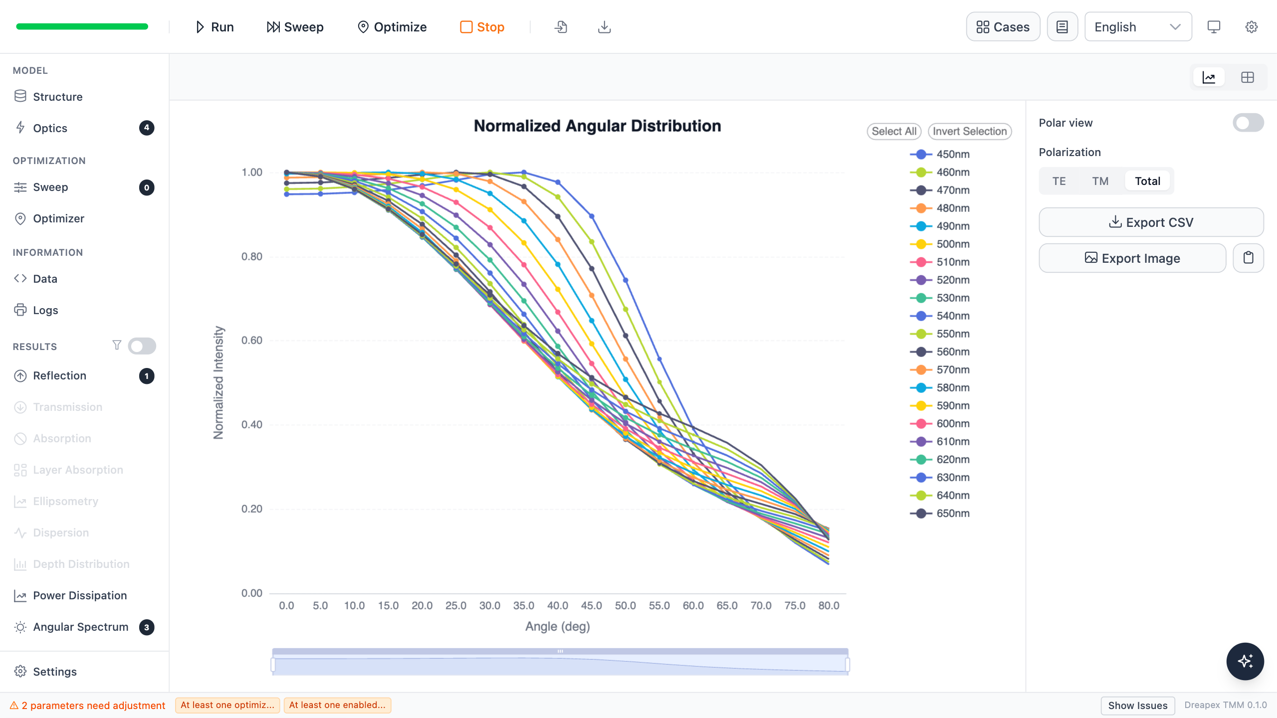
Normalized Angular Distribution
Normalization definition: each (wavelength, polarization) series is scaled so its peak = 1 across angles. TE / TM / Total are normalized independently.
The x-axis is locked to Angle (deg); the y-axis is Normalized Intensity. Line chart is the default; in line mode the Polar Toggle is available.
This view uses the same underlying data as Angular Spectrum, but normalization removes the absolute intensity difference between wavelengths, making it suitable for comparing the shape of emission lobes across different wavelengths.
Controls
Common export and copy controls (Export CSV, Export Image, Copy Image) are described in Basic Optical Results. Controls specific to this page and its derived views are:
| Control | Function |
|---|---|
| Polarization SelectButton | Switch TE / TM / Total in two- or three-dimensional derived charts; one-dimensional derived charts show all three in the legend |
| X-axis selector (Intensity 2D mode) | Switch the x-axis between Angle and Wavelength |
| Chart type | Switch a two-dimensional result between Line and Heatmap |
| Polar Toggle | Switch an angular distribution to a polar plot |
| Status summary | Count valid, warning, and missing points for the current derived metric |
| Legend select / invert | Click a legend item to isolate one series; click again to restore all |
Next
After reviewing intensity and spectral width, go to Intensity Color for CIE chromaticity and visible-color output. If Peak Wavelength jumps or FWHM reports a warning, return to the raw spectrum on this page first.