Intensity Color
OLED emission color can change strongly with output angle: a device that appears yellow-green on-axis may shift toward cyan-green off-axis. Intensity Color converts the emission spectrum at each angle into chromaticity coordinates and color descriptors for evaluating that angular shift.
Intensity wavelength and angle modes in Emission Detectors.Example Setup
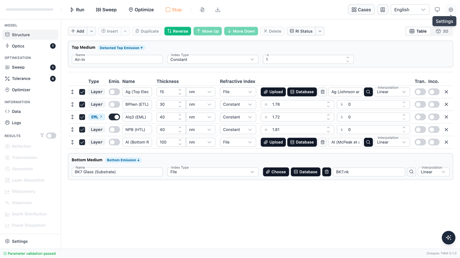
This page uses the top-emitting OLED case. Emission is detected through the semitransparent Ag top electrode. The Alq₃ emissive layer uses a broad synthetic spectrum with a peak near 530 nm and a red tail.
Structure direction: top medium → bottom medium
| Object | Thickness | Refractive-index setup |
|---|---|---|
| Top medium | — | Air, n = 1 |
| Ag top electrode | 15 nm | Refractive-index database |
| BPhen electron-transport layer | 30 nm | Constant, n = 1.78 |
| Alq₃ emissive layer | 40 nm | Constant, n = 1.72, with an Alq₃ emitter |
| NPB hole-transport layer | 40 nm | Constant, n = 1.81 |
| Al bottom reflector | 100 nm | Refractive-index database |
| Bottom medium | — | BK7 substrate, file-based refractive index |
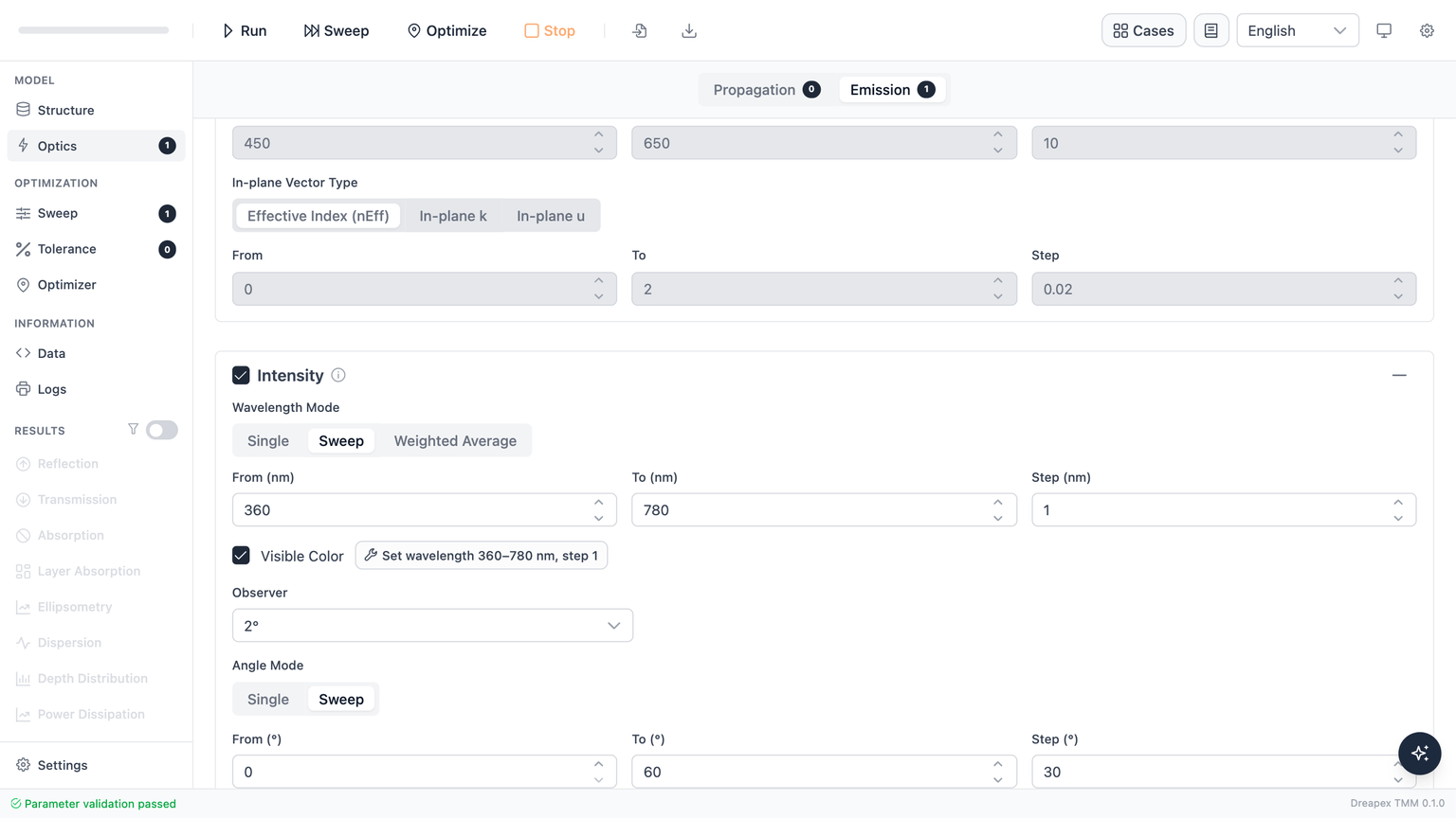
Optics enables only the Intensity detector in the Emission lane. The wavelength grid uses 1 nm, and three output angles make on-axis and off-axis emission directly comparable.
| Parameter | Value |
|---|---|
| Detector | Intensity |
| Wavelength mode | Sweep |
| Wavelength range | 360–780 nm |
| Wavelength step | 1 nm |
| Visible Color | Enabled |
| Observer | 2° |
| Angle mode | Sweep |
| Angle range | 0–60° |
| Angle step | 30° |
Generation Requirements
Intensity Color requires all of the following:
- Enable the
Intensitydetector. - Set
Wavelength ModetoSweep. - Set the wavelength range exactly to
360–780 nm. - Use a wavelength step no greater than
5 nm. - Enable
Visible Color.
The 360–780 nm / ≤ 5 nm grid is a Dreapex TMM generation requirement, not a claim of physical-measurement conformity with ISO/CIE 11664-3:2019.
Set wavelength 360–780 nm, step 1 applies the detector, wavelength, and color settings in one action. Emission uses the emitter spectrum in the emissive layer; it neither requires nor reads the Propagation lane's Incident Spectrum.
Intensity is enabled, the wavelength mode is a Sweep covering 360–780 nm, and the emissive layer produces visible output; Single and Weighted Average do not retain the wavelength-resolved spectrum required for color integration. If only some angles have no visible emission, the remaining angles still appear and the page reports the omitted count.Emission-Spectrum Convention
Each result row represents one output angle. Dreapex TMM first obtains intensity versus wavelength at that angle, then integrates it with the selected observer's color-matching functions to produce XYZ, xy, and the other color quantities. It is neither one color integrated over every output direction nor a physical measurement report.
The emitter's Spectrum Unit defines the input convention:
Poweris used directly as a relative radiant-power spectrum.Probabilityis converted to a power spectrum using photon energy before color calculation.
For one emitter, a common scaling from Conversion Efficiency or Multiplication Factor does not change chromaticity. With multiple emitters, their relative efficiencies and factors change the mixed spectrum and therefore the mixed color.
Chromaticity Diagram
The diagram draws one point for each angle with visible emission. In this example, the 0°, 30°, and 60° points move across the green region, directly showing angular color shift caused by the microcavity stack.
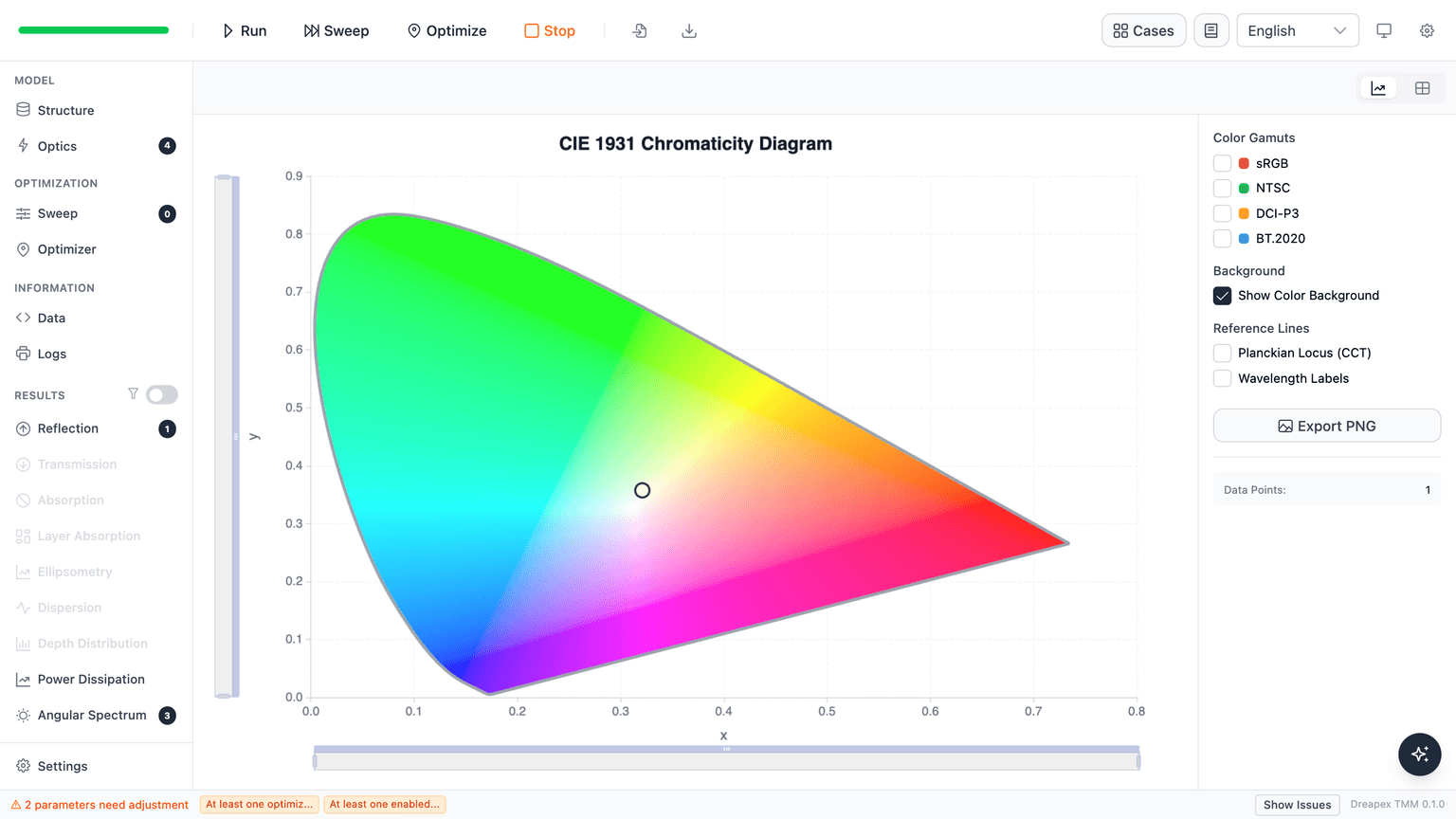
Connect Data Points joins the angle points to show the direction of color travel. All points share one brightness scaling, so their relative brightness can be compared. The swatches and sRGB values remain screen previews rather than absolute luminance or radiometric intensity.
Angles without visible emission are omitted and counted in a note below the result. The chart draws at most 2,000 points; when parameter combinations multiplied by angles exceed that limit, use the table and CSV.
Color Data Table
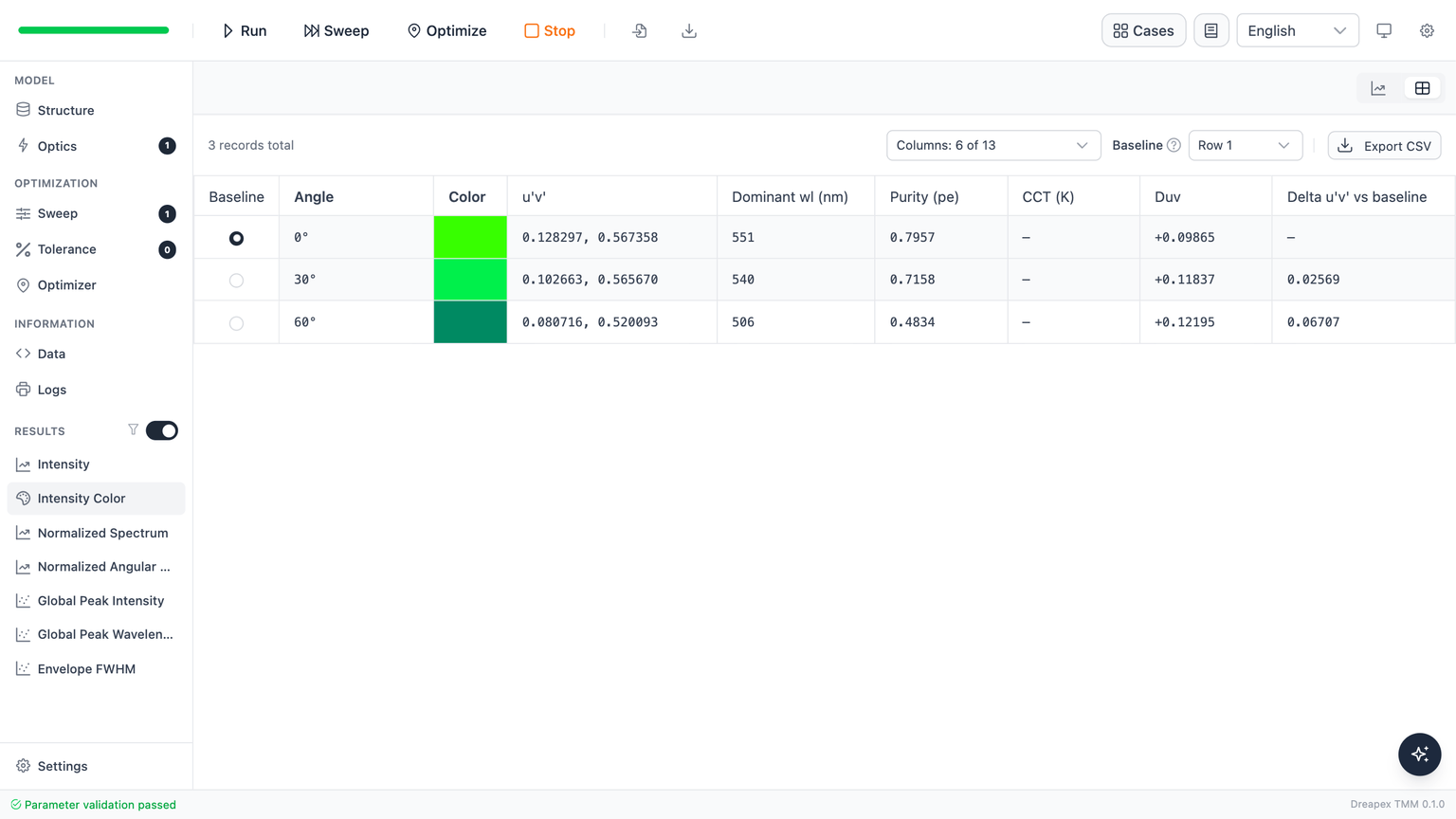
In a single run, table view shows one row per output angle. In a parameter Sweep, each row represents a parameter-combination-and-angle pair; a separate Angle column remains visible for multi-angle results. Columns controls only the on-screen view, while Export CSV always exports the complete result.
| Calculation | Dreapex TMM output | Standard or primary reference | Scope |
|---|---|---|---|
| Standard observer | 2°, 10° | ISO/CIE 11664-1:2019 | Select the visual-field observer required by the experiment or product specification; it is not an output angle or accuracy grade |
| Tristimulus and chromaticity | XYZ, xy, xyY | ISO/CIE 11664-3:2019 | Records simulated chromaticity at each output angle; does not establish physical-measurement conformity |
| Uniform chromaticity and angular shift | u′v′, Delta u′v′ | ISO/CIE 11664-5:2024, CIE TN 001:2014 | Compares chromaticity separation between angles or parameter combinations; no universal pass/fail threshold applies |
| Hue and purity | dominant wavelength, complementary wavelength, excitation purity | CIE e-ILV term definitions | Describes the perceptual hue direction and purity of a chromaticity point; dominant wavelength is not the spectral peak |
| White-light descriptors | CCT, Duv | Ohno (2014), CIE TN 013:2022 | Available only with the 2° observer; use chromaticity coordinates and dominant wavelength first for saturated colors |
| Display preview | Linear sRGB, sRGB, sRGB 8-bit, Hex | Screen-display mapping, not a standards-conformity metric | Uses shared exposure to compare relative color and brightness across angles; does not represent absolute luminance or radiometric intensity |
L*a*b*, C*ab, h_ab, Y/Yi, or Delta E00; angular color shift uses Delta u′v′, which requires no reference white.Color Metrics and Display
Baseline Row and Angular Color Shift
The table uses the first row as Baseline by default. Select another row with its radio button or the toolbar dropdown; Delta u′v′ immediately updates relative to the new baseline.
Delta u′v′ is the straight-line distance in the CIE 1976 u′v′ plane. CIE TN 001:2014 recommends it for describing angular chromaticity differences of light sources, but it defines no universal pass/fail threshold; apply the limit set by the display, lighting-product, or customer specification. For physical angle-resolved spectral and color measurement, refer to CIE 239:2020.
With 0° as the baseline, this example gives Delta u′v′ = 0.02569 at 30° and 0.06707 at 60°. Use these values together with the direction shown in the diagram instead of treating sRGB swatches as quantitative evidence.
Dominant Wavelength and Excitation Purity
Dominant wavelength describes the perceptual hue direction from equal-energy white E to the emission chromaticity point. It is not the spectral peak reported by Global Peak Wavelength:
- A plain number is the dominant wavelength on the spectral locus, in nanometres.
- A trailing
cdenotes the complementary wavelength for a purple-line color. - When excitation purity
pe < 0.01, chromaticity is too close to the achromatic reference for a stable hue direction, so wavelength is shown as—.
Dominant wavelength describes perceived hue; peak wavelength locates the maximum of the spectrum. They may be close for narrow, single-peak emission but should not be interchanged for broad, multi-peak, or strongly microcavity-shaped spectra.
CCT and Duv
CCT and Duv are available only with the 2° observer and use the Ohno (2014) method; see CIE TN 013:2022 for their scope:
Duv > 0places chromaticity above the Planckian locus and is typically greener near white;Duv < 0places it below the locus and is typically pinker near white.CCTis shown only when|Duv| <= 0.05; outside that domain,CCTis—whileDuvremains available.- When
0.006 < |Duv| <= 0.05,CCTcarries*. The±0.006reference band is a tool-chosen visual hint, not a binning or compliance verdict.
All three angles in this example have |Duv| > 0.05, so the table correctly keeps Duv and displays — for CCT. Highly saturated green emission lies far from the Planckian locus and cannot be described meaningfully by one correlated color temperature.
Observer and Sampling
2° / 10° denote the standard observers for different visual-field conditions defined by ISO/CIE 11664-1:2019, not output angles or accuracy grades. Select the observer required by the experiment or product specification, then rerun after switching.The observer is frozen at run time. Rerun after switching between 2° and 10°:
- 2° uses the CIE 1931 diagram and provides
CCT / Duv. - 10° uses the CIE 1964 locus and hides gamut triangles, preset white points, and
CCT / Duv.
Wavelength step may be <= 5 nm, but use 1 nm for color comparison. When the actual result grid is coarser than 1 nm, the page shows a nonblocking coarse-sampling note. Narrow emission peaks, especially those with FWHM below about 10 nm, are more sensitive to grid placement; the UI warning gives a possible shift on the order of Delta u′v′ = 0.005.
Next
Compare dominant wavelength with the spectral peak in Intensity Spectrum Peaks and Envelope FWHM, then use Mode to relate angular color shift to outcoupling and loss channels.