Swept Emission
This guide explains how to use Sweep to vary emitter spectrum, position, orientation, and efficiency, then read the resulting emission changes. Afterward, you can compare how emitter settings affect intensity, color, and mode distribution.
Sweepable emitter properties
In the Sweep page, select the emitter under the target emissive layer, then choose the property to sweep:
| Property (as shown in sweep selector) | Range |
|---|---|
Dipole Position | 0–1 (relative position inside layer) |
Dipole Orientation (perpendicular fraction) | 0–1 |
Emission Zone Width | > 0; unit follows the Width unit selector |
Emission Zone Sample Count | Integer 1–100 |
Conversion Efficiency | 0–1 |
Quantum Efficiency | 0–1 |
Multiplication Factor | ≥ 0 |
Lifetime | > 0; unit follows the Lifetime unit selector |
Properties that cannot be swept: spectrum type, dipole orientation type, distribution type, all unit fields, all file fields.
Multiple emissive layers (EML) can coexist in one structure, and each emitter in each EML layer can be configured independently as a sweep variable; emitters inside Layer Group-nested layers are equally supported.
Interpreting a Conversion Efficiency sweep
Conversion Efficiency is the probability that recombining charges form emitting excitons; it is not the non-radiative channel on the Mode page. Sweeping it affects result pages differently:
| Scenario | Intensity / Power Dissipation | Mode | Intensity Color |
|---|---|---|---|
| One emitter | Intensity scales linearly with Conversion Efficiency | Relative channel composition and NRA are unchanged | Chromaticity coordinates are unchanged |
| Several emitters | The swept emitter's contribution changes | Combined Mode changes with the relative emitter weights | The mixed spectrum and chromaticity can change |
Multiplying every emitter's Conversion Efficiency by the same constant leaves the relative multi-emitter Mode composition unchanged, while raw intensity and power dissipation still scale with source strength. If conversion loss is included in a full device-efficiency budget, keep it separate from exciton non-radiative loss on the Mode page.
Swept result views
After a sweep run completes, each emission result page in the sidebar switches to swept display mode. Available chart types depend on the combination of sweep dimensions and internal data axes:
| Sweep dimensions and data shape | Available chart types |
|---|---|
| 1 sweep parameter, X = sweep axis | Line only; Mode view defaults to Stacked Area |
| 1 sweep parameter, internal axis is wavelength or angle | Line + Heatmap |
| 2 sweep parameters + 1 internal axis | Line + Heatmap + 3D Scatter |
| 2 sweep parameters, Normalized views | 3D Scatter only (forced) |
| Total dimensions ≥ 4 | Table only (charts unavailable) |
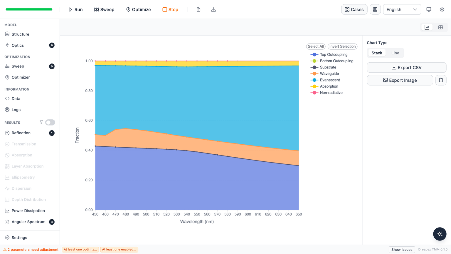
Mode view default: when a sweep is active, the Mode result page defaults to a Stacked Area chart showing all 7 mode channels (Top Outcoupling, Bottom Outcoupling, Substrate, Waveguide, Evanescent, Absorption, Non-radiative) as the sweep parameter varies; channel fractions sum to approximately 1. The view can be switched to Line mode to inspect individual channels.
Normalized views (Normalized Spectrum / Normalized Angular Distribution): with 2 sweep parameters, the chart type is forced to 3D Scatter — no other chart option is available — because all series must be rendered simultaneously.
Next
Detailed documentation for each emission result page: