Microcavity Effect
The same OLED can look correct on axis yet appear greener, bluer, or more saturated from the side. The emitter peak does not move with the viewer; the device changes how it selects wavelengths and angles.
Metal electrodes, semitransparent electrodes, and refractive-index boundaries form a planar microcavity. Direct and reflected emission interfere coherently, making spectrum, color, angular distribution, and outcoupling efficiency depend on film thickness and viewing angle.
Reflection and Optical Path Form the Cavity
The emitter and one reflector produce wide-angle interference, while repeated round trips between two reflecting boundaries produce multiple-beam interference. The former is controlled mainly by the emitter-to-mirror distance; the latter is controlled mainly by total cavity length and the reflectance of both sides.
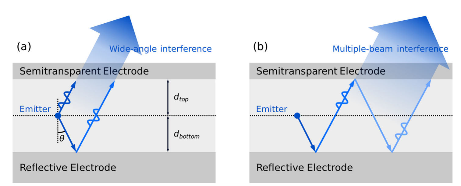
Using an average refractive index for the cavity optical path, a wide-angle resonance involving the lower reflector can be written as
The multiple-beam resonance between two reflectors is
Here, is vacuum wavelength, is an effective cavity refractive index, and are the distances from the emitter to the top and bottom reflectors, is the propagation angle inside the cavity, and are the two reflection phases, and is an integer resonance order. In a real device, both and the reflection phases vary with wavelength, so the exact resonance must be calculated through the full stack.
Spectral and Color Selection
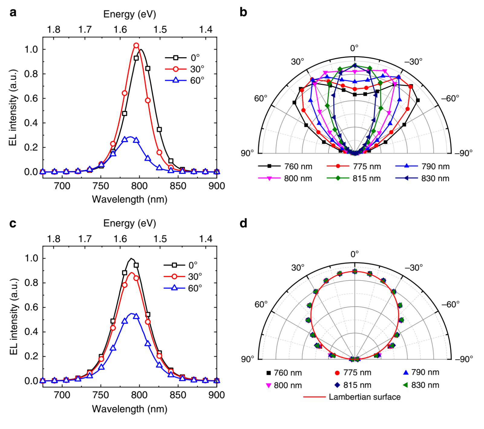
Constructive interference enhances wavelengths satisfying the resonance condition, while destructive interference suppresses others. A weak microcavity usually produces broad spectral modulation. Increasing mirror reflectance raises the cavity finesse, narrows the emission peak, and increases color saturation. Changing a transport-layer thickness, emission position, or electrode thickness changes the optical path or reflection phase, so identical emitting materials can produce substantially different EL spectra.
The microcavity acts as an angle-dependent optical filter on the material PL spectrum. Conceptually,
where is the outcoupled electroluminescence spectrum, is the intrinsic emitter spectrum, and is the layered emission response at wavelength and external angle . The proportionality omits absolute source strength, polarization, and spatial-distribution factors.
Off-Axis Color Shift
If reflection-phase dispersion is neglected, a fixed resonance order approximately follows
Here, is the wavelength of resonance order . As the viewing angle grows, the internal angle also grows and falls, so the resonance usually shifts toward shorter wavelengths. A red or white device may therefore lose long-wavelength weight off axis and appear greener or bluer.
A green off-axis tint is not a universal OLED rule. Its direction depends on the cavity length, emitter spectrum, reflection phase, color filter, and angular response of each RGB subpixel. Simulation should compare the full angle-resolved spectrum or chromaticity coordinates rather than tracking one peak alone.
Formation and Breakdown of Lambertian Emission
An ideal Lambertian surface has direction-independent radiance. The projected area of a finite surface element decreases by , so its radiant intensity follows
where is radiant intensity at angle from the surface normal and is the normal intensity. The perceived radiance remains constant, while the power from the whole surface element into unit solid angle falls as .
The pattern of a single electric dipole is not Lambertian. An OLED approaches Lambertian emission through statistical superposition of many dipole positions and orientations, in-plane rotational symmetry, a cavity response with weak angular selectivity, and scattering or incoherent averaging in the device. A strong microcavity selects particular wavelengths and angles, producing a clear departure from the cosine law.
Angular Distribution and Efficiency
A microcavity can redirect power from large-angle or guided regions into the escape cone and thereby increase LEE. The optimal pattern need not place all intensity at , because angular integration uses
where is polar angle, is azimuth, and is solid angle. The factor is small close to the normal, so an extremely narrow on-axis peak does not necessarily maximize total outcoupling.
A stronger microcavity also introduces trade-offs:
- Higher reflectance can strengthen constructive interference and spectral purification while reducing electrode transmittance.
- Repeated round trips increase absorption opportunities in metals and lossy layers.
- Bringing the EML closer to a metal strengthens evanescent and SPP coupling.
- The thickness maximizing on-axis color can differ from the thickness maximizing angle-integrated efficiency.
- Narrow-angle emission can benefit some optical systems but reduce display viewing-angle uniformity.
Microcavity design should therefore inspect angle-resolved spectra, color, normalized angular distribution, and optical modes together. Optimizing the normal spectrum alone can produce excellent color without the highest total outcoupling.
Next Step
Continue with Power Dissipation and Optical Modes to convert the cavity's wavelength and angular selection into integrable energy channels.
Reference
- Ismail, N.; Kores, C. C.; Geskus, D.; Pollnau, M. Fabry–Pérot Resonator: Spectral Line Shapes, Generic and Related Airy Distributions, Linewidths, Finesses, and Performance at Low or Frequency-Dependent Reflectivity. Opt. Express 2016, 24, 16366.
- Dodabalapur, A.; Rothberg, L. J.; Jordan, R. H.; Miller, T. M.; Slusher, R. E.; Phillips, J. M. Physics and Applications of Organic Microcavity Light Emitting Diodes. J. Appl. Phys. 1996, 80, 6954–6964.
- Hofmann, S.; Thomschke, M.; Lüssem, B.; Leo, K. Top-Emitting Organic Light-Emitting Diodes. Opt. Express 2011, 19, A1250.
- Miao, Y.; Cheng, L.; Zou, W.; et al. Microcavity Top-Emission Perovskite Light-Emitting Diodes. Light Sci. Appl. 2020, 9. https://doi.org/10.1038/s41377-020-0328-6
- Poitras, D.; Kuo, C. C.; Py, C. Design of High-Contrast OLEDs with Microcavity Effect. Opt. Express 2008, 16, 8003–8015.
- Deng, L.; Zhou, H.; Chen, S.; et al. Influences of Wide-Angle and Multi-Beam Interference on the Chromaticity and Efficiency of Top-Emitting White Organic Light-Emitting Diodes. J. Appl. Phys. 2015, 117. https://doi.org/10.1063/1.4913482