Are More Layers Better? Comparing Dichroic Performance and Structural Cost
This tutorial continues Separate Blue-Green and Red Light: Design a 45° Dichroic Beamsplitter and reuses the same materials, target bands, and 45° incidence condition.
The most direct way to increase blue-green reflection from a 45° dichroic beamsplitter is to add more TiO₂/MgF₂ pairs. More layers also increase total thickness, however, and may reduce red transmission or polarization performance, so pair count alone cannot identify the better design.
This tutorial optimizes 4-, 6-, and 8-pair stacks using the same materials, objectives, thickness ranges, and algorithm. You will compare blue-green reflection, red transmission, polarization, total thickness, and variable bounds, then select the simplest structure that meets the specification.
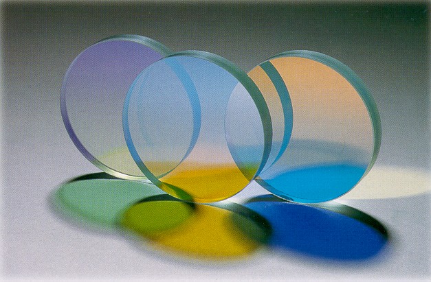
Fix the comparison rules first
Only Repeat Count changes among the three candidates. All other settings remain identical:
| Item | Common setting |
|---|---|
| Period materials | TiO₂ / MgF₂ |
| Initial period thicknesses | 56 nm / 100 nm |
| Pair count | 4, 6, 8 |
| Incidence condition | 45°, unpolarized light, pRatio=0.5 |
| Blue-green objective | Maximize mean reflectance from 450–520 nm |
| Red objective | Maximize mean transmittance from 620–700 nm |
| TiO₂ range | 25–80 nm |
| MgF₂ range | 70–140 nm |
| Teaching specification | Unpolarized mean values in both bands must be at least 90% |
The two optical metrics are
Here, is the mean reflectance in the blue-green band, is the mean transmittance in the red band, and are the reflectance and transmittance at wavelength , is the sample index, and and are the numbers of samples in the two bands.
If each period contains one high-index layer H and one low-index layer L, and the pair count is , the number of coating layers and the total coating thickness are
Here, is the number of coating layers, is the total physical coating thickness excluding the substrate, and and are the thicknesses of one TiO₂ layer and one MgF₂ layer, respectively, in nm.
Build three candidates from a common starting point
The incident medium is air. Below the coating is a 1 mm incoherent glass substrate, and the bottom-medium refractive index is 1.52. All three candidates start from 56 nm TiO₂ and 100 nm MgF₂; only Repeat Count changes.
| Candidate | Repeat Count | Initial TiO₂ thickness | Initial MgF₂ thickness |
|---|---|---|---|
| 4 pairs | 4 | 56 nm | 100 nm |
| 6 pairs | 6 | 56 nm | 100 nm |
| 8 pairs | 8 | 56 nm | 100 nm |
Restore this common pair of initial thicknesses before every optimization. Otherwise, a later candidate inherits the optimum of an earlier one and the candidates no longer share the same starting point.
Optimize each candidate instead of comparing initial structures
In Optics, set 400–750 nm with a 1 nm step, 45° incidence, and unpolarized light. Add two equally weighted objectives in Optimizer:
- Maximize mean
Reflectancefrom 450–520 nm with a 5 nm step; - Maximize mean
Transmittancefrom 620–700 nm with a 5 nm step.
For each candidate, use only the two shared thickness variables for TiO₂ and MgF₂ within the period. Use Nelder–Mead for every optimization, with at most 280 evaluations and an initial simplex scale of 0.08.
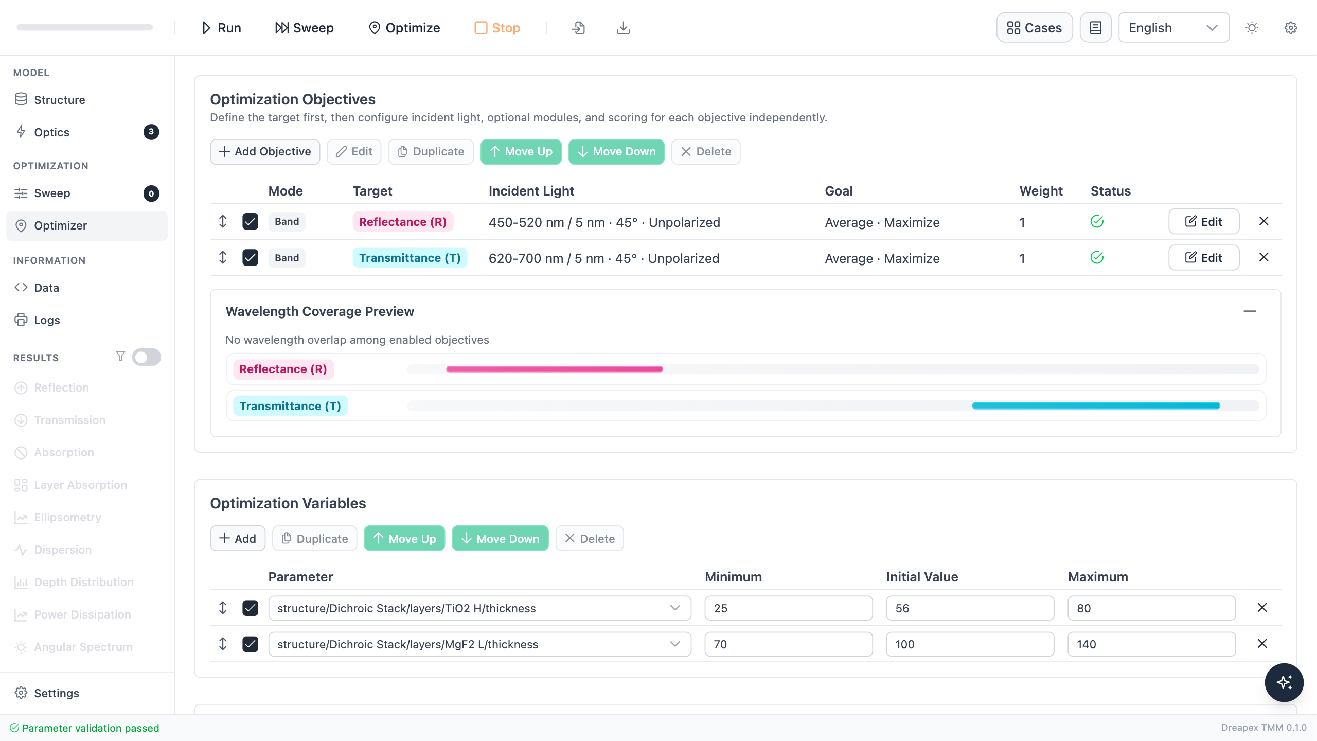
The two objectives constrain blue-green reflection and red transmission, while the variables control the TiO₂ and MgF₂ thicknesses in one period. Objective weights and variable ranges remain unchanged when pair count changes.
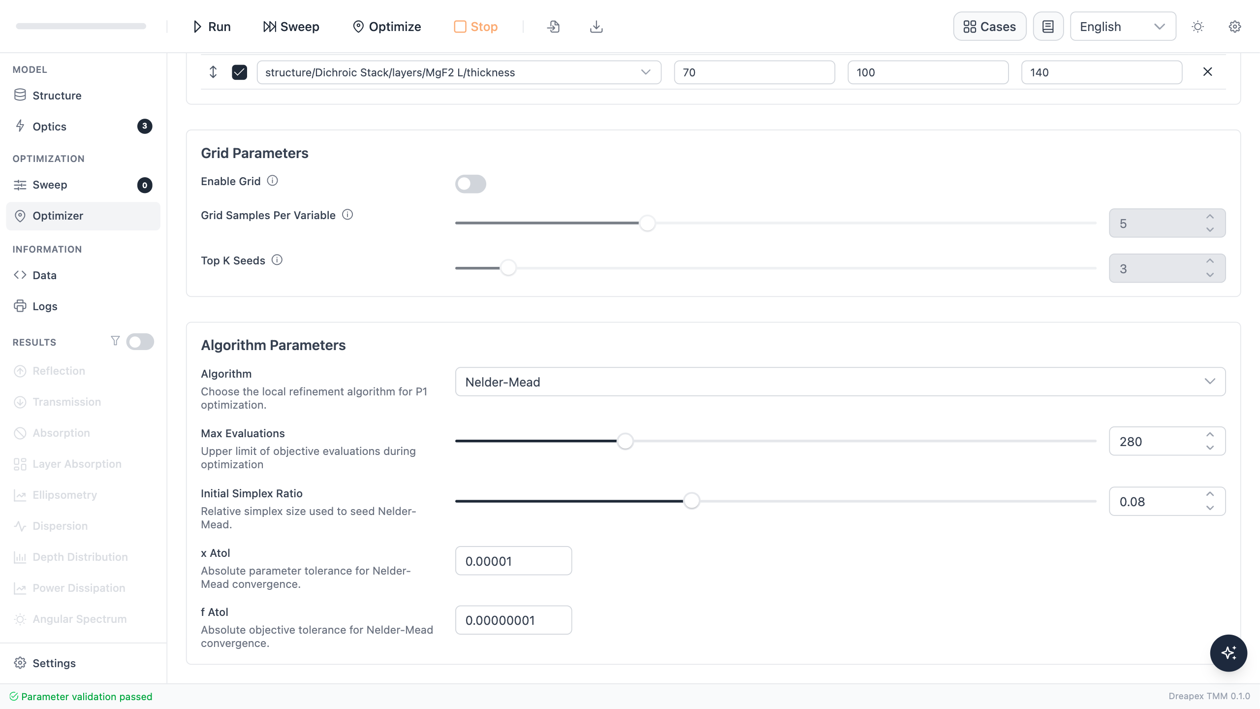
All three runs use the same algorithm and evaluation limit so that differences in search settings are not mistaken for pair-count effects.
Run the three optimizations separately and check each Optimization Report. The optimization objectives use 5 nm sampling, whereas final acceptance uses 1 nm spectra, so the report values and final table will differ slightly.
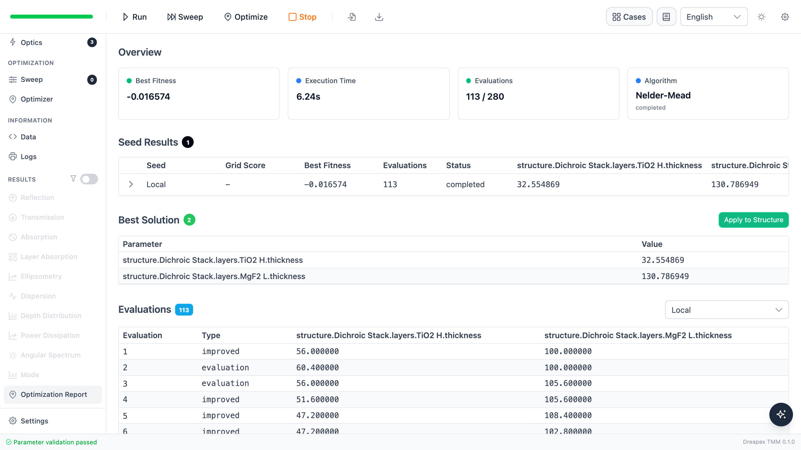
Both optimized thicknesses for the four-pair candidate remain inside their permitted ranges, so the result can be applied directly before fine-step acceptance testing.
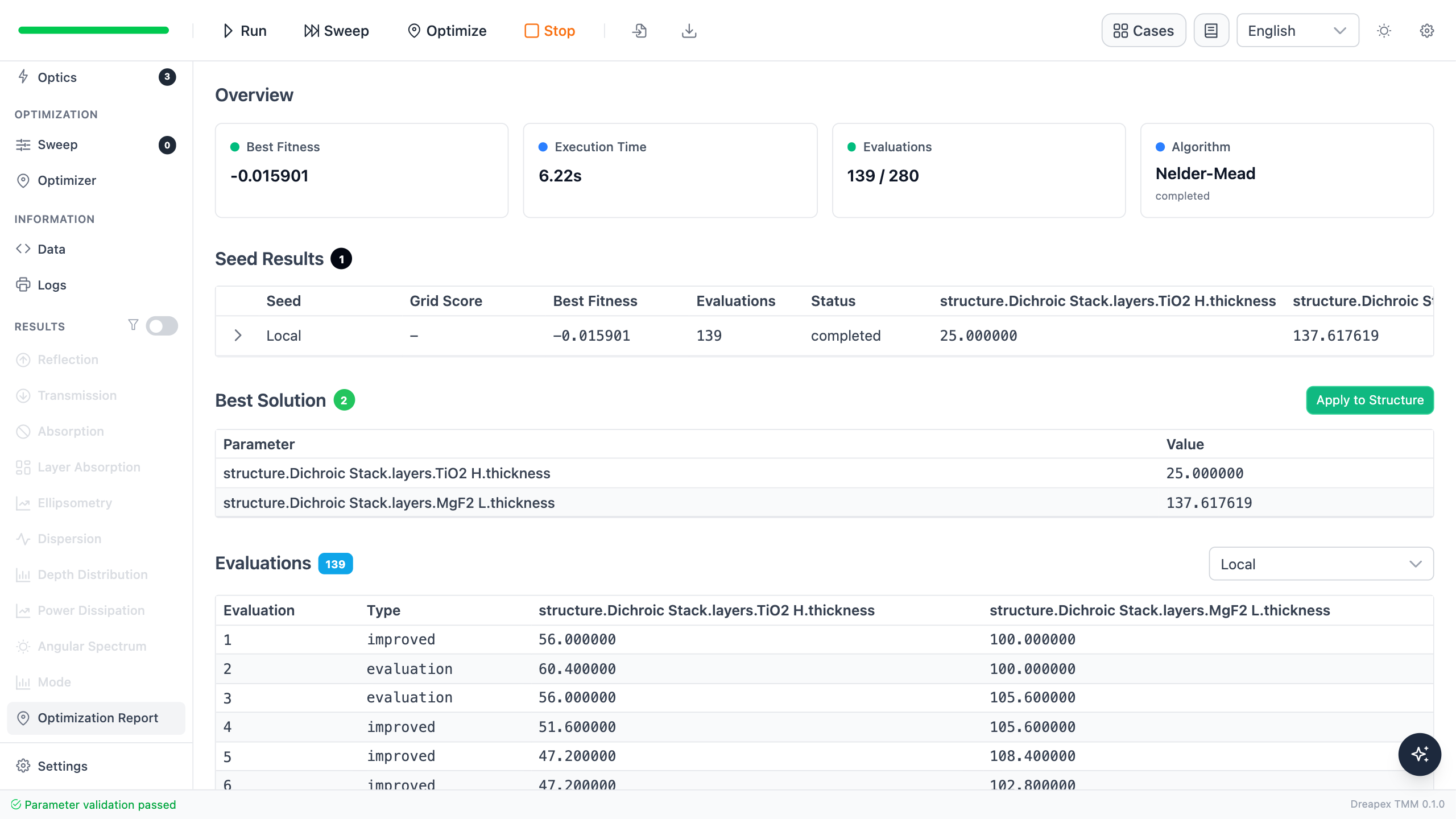
The six-pair result pushes TiO₂ to its 25 nm lower bound. Its reported objective values must therefore be judged together with the bound condition and the final 1 nm spectrum.
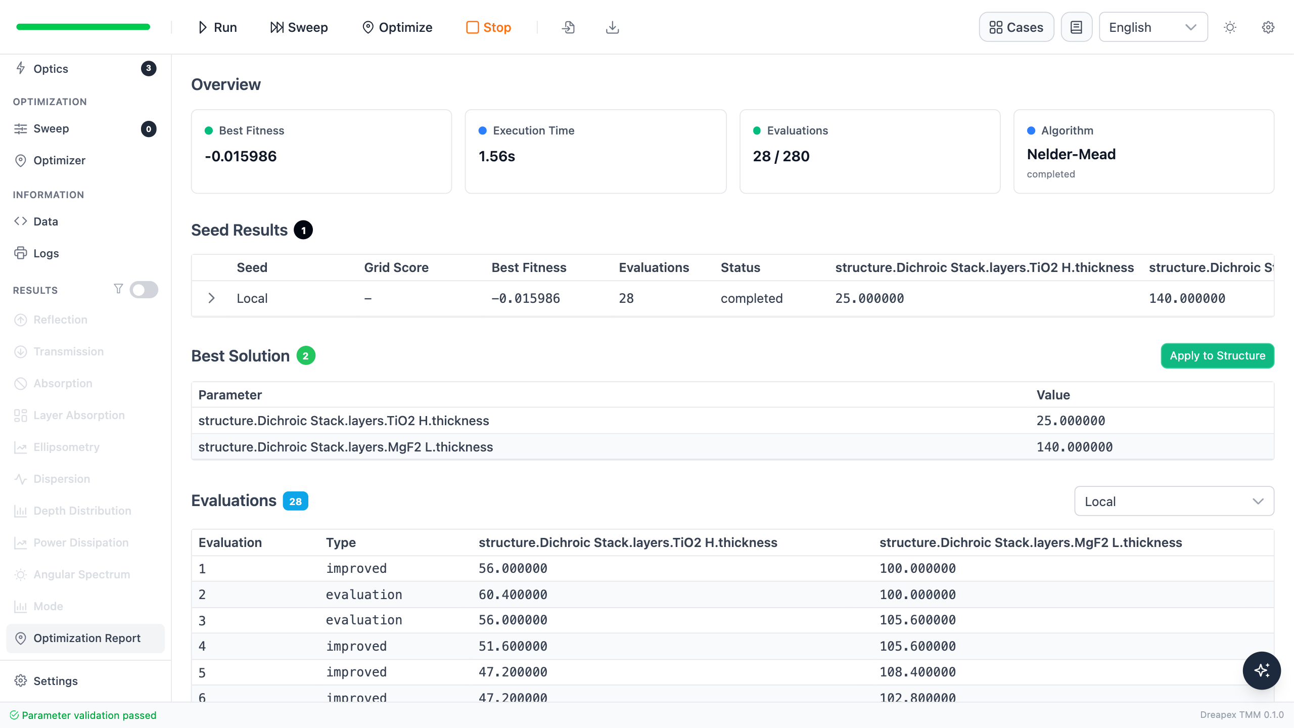
For eight pairs, TiO₂ and MgF₂ stop at their lower and upper bounds, respectively. The objective has converged, but the permitted thickness ranges constrain further trade-offs.
Apply the optima and verify the structures
Click Apply to Structure in each report, then run the forward calculation again with a 1 nm step. The optimized period thicknesses are:
| Pair count | Optimized TiO₂ thickness | Optimized MgF₂ thickness | Layer count | Total coating thickness |
|---|---|---|---|---|
| 4 | 32.555 nm | 130.787 nm | 8 | 653.37 nm |
| 6 | 25.000 nm | 137.618 nm | 12 | 975.71 nm |
| 8 | 25.000 nm | 140.000 nm | 16 | 1320.00 nm |
Each Layer Group now has a different pair count and optimized thicknesses. Check each Structure overview and open Edit Group to verify the group name, Repeat Count, layer order, and material parameters.
Four-pair candidate

The structure overview contains one periodic group with Repeat Count set to 4, giving eight functional layers. At 653.37 nm, it is the thinnest of the three candidates.
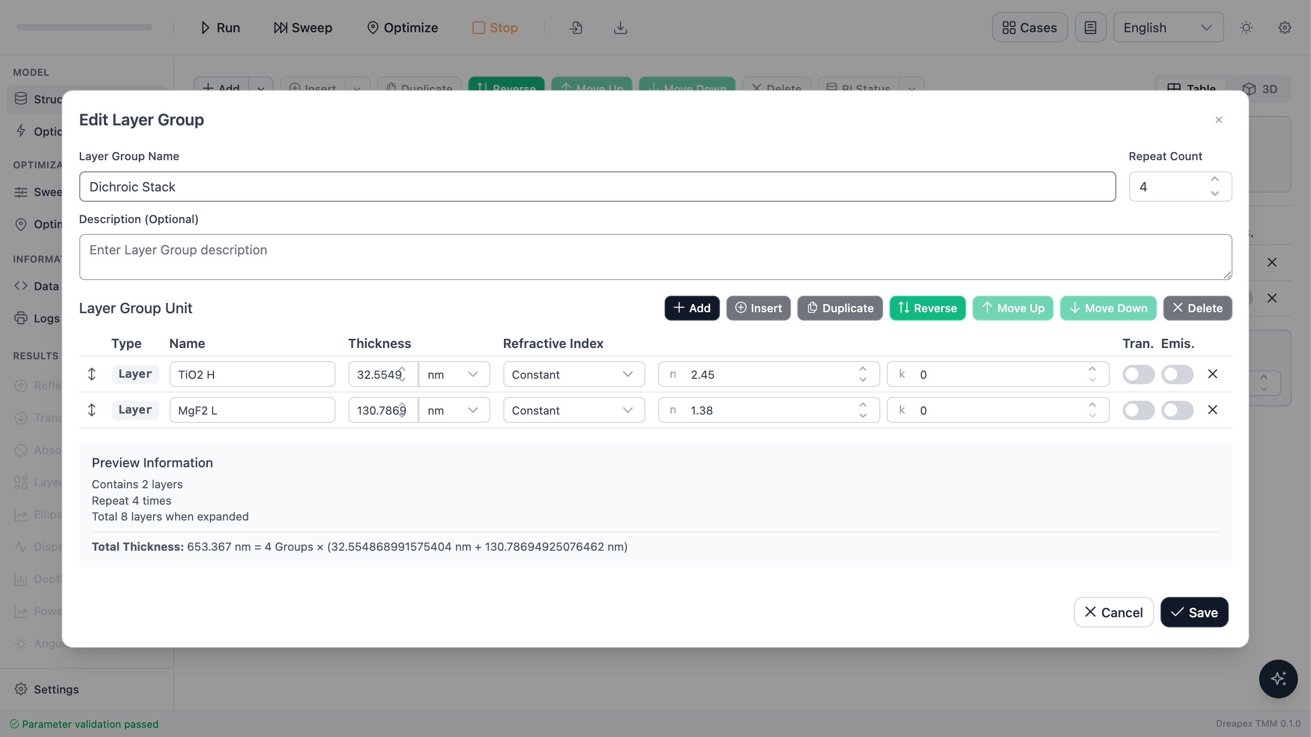
The TiO₂ and MgF₂ layers are 32.555 nm and 130.787 nm thick, respectively. Neither variable stops at a permitted bound.
Six-pair candidate

Increasing the pair count to 6 gives 12 functional layers and raises total thickness to 975.71 nm. The basic alternating high- and low-index structure remains unchanged.
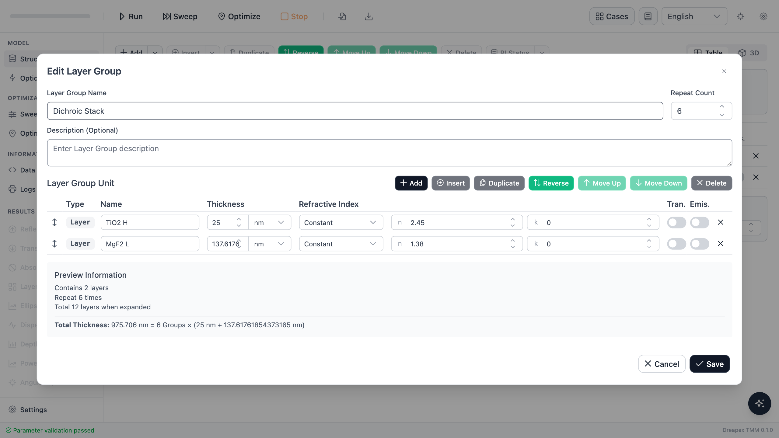
The optimized TiO₂ thickness is 25.000 nm, exactly at its lower bound, while MgF₂ is 137.618 nm thick. This bound condition must be considered together with the final spectrum.
Eight-pair candidate

The eight-pair candidate contains 16 functional layers and reaches a total thickness of 1320.00 nm, about twice that of the four-pair candidate.
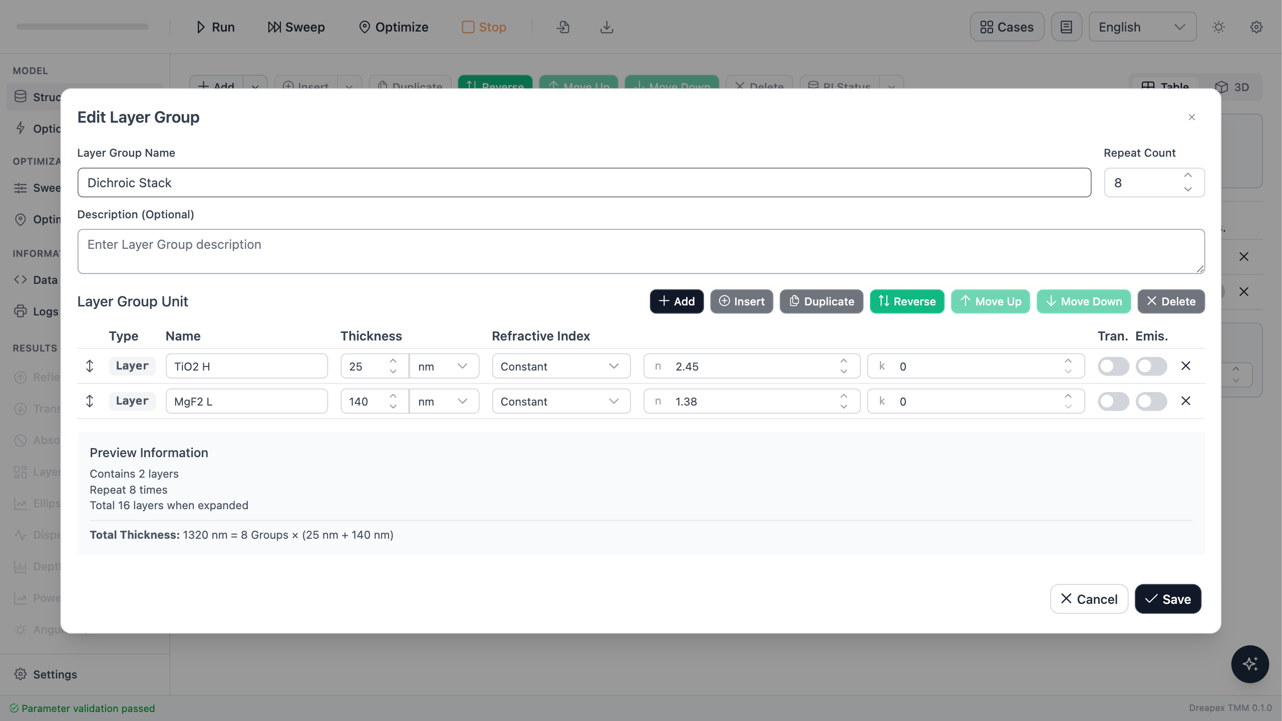
TiO₂ stops at its 25.000 nm lower bound and MgF₂ at its 140.000 nm upper bound. Both variables reaching bounds indicates that this periodic structure has little room left to balance the two target bands within the permitted thickness ranges.
Compare performance, thickness, and bounds together
| Pair count | Blue-green mean | Blue-green minimum | Red mean | Red minimum | Total thickness | Variables at bounds |
|---|---|---|---|---|---|---|
| 4 | 91.228% | 87.100% | 91.160% | 78.693% | 653.37 nm | None |
| 6 | 91.824% | 75.787% | 90.915% | 76.209% | 975.71 nm | TiO₂ at lower bound |
| 8 | 96.332% | 81.602% | 87.882% | 81.419% | 1320.00 nm | TiO₂ at lower bound; MgF₂ at upper bound |
Each structure is rerun with a 1 nm step after applying its optimized thicknesses. The reflectance spectra show the trade-off directly: more pairs raise average blue-green reflectance, but they do not automatically remove transition-band ripple or guarantee lower reflection in the red band.
Four pairs: both bands meet the mean-value specification
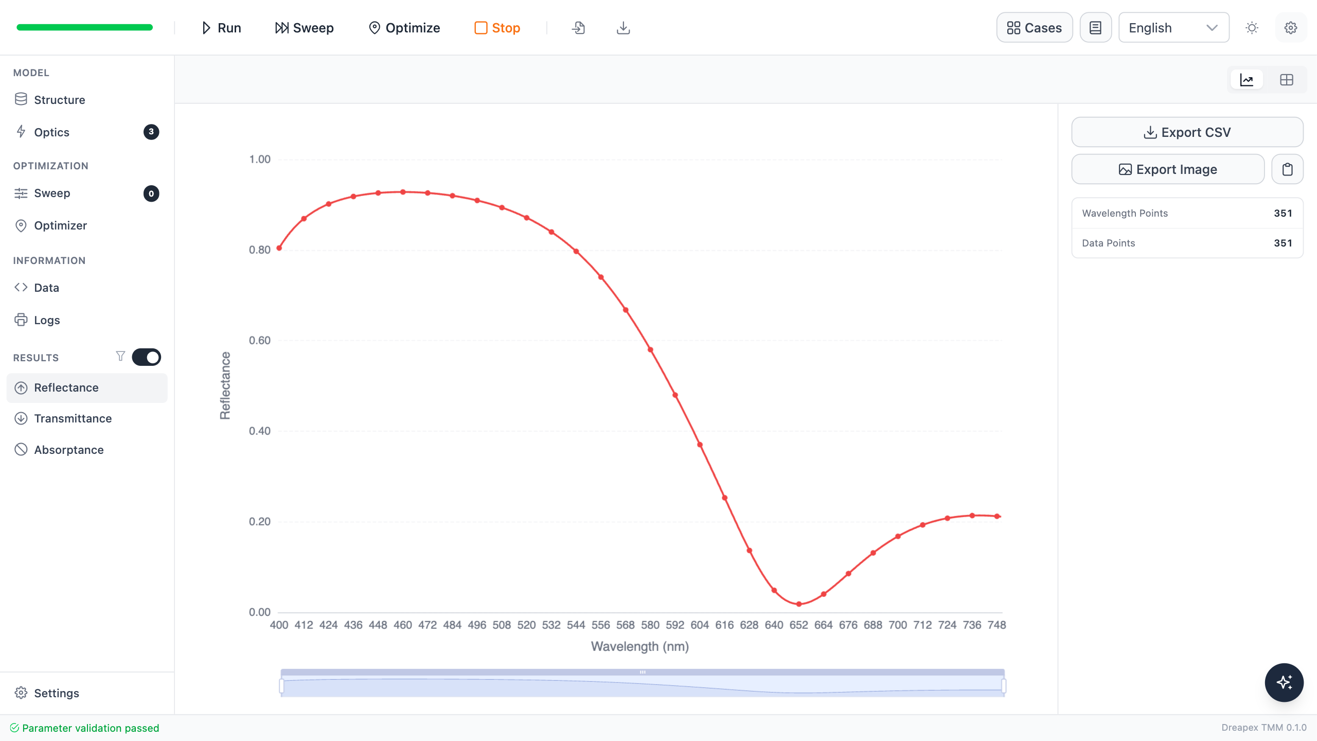
The four-pair design reaches 91.228% mean blue-green reflectance and 91.160% mean red transmittance, so both means pass the 90% teaching specification. Its minimum blue-green reflectance is 87.100%, showing that a band mean does not represent every wavelength in the band.
Six pairs: a small gain in the mean but a lower band minimum
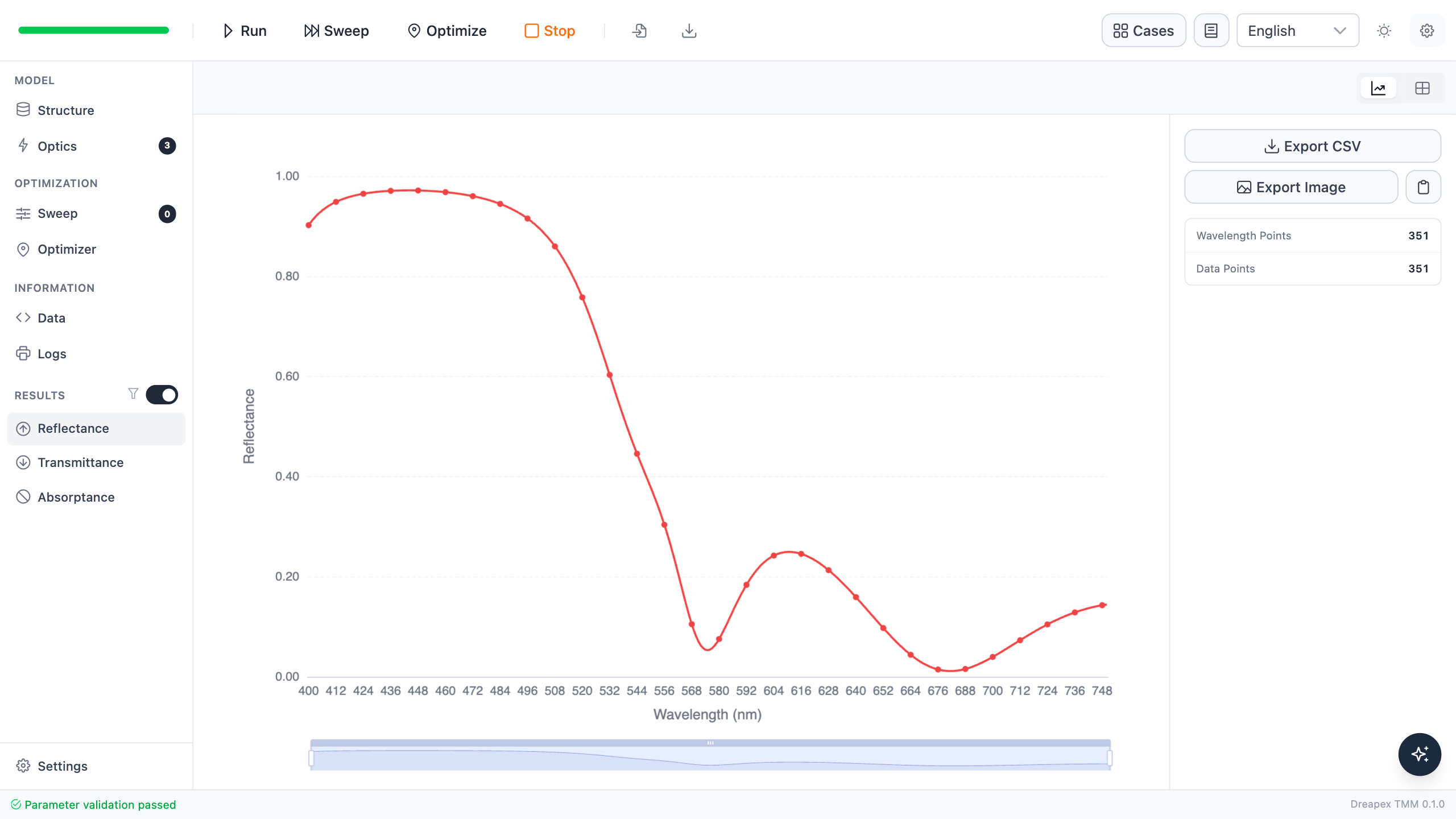
The six-pair design raises mean blue-green reflectance to 91.824%, but its minimum falls to 75.787%; mean red transmittance is 90.915%. Compared with four pairs, two extra pairs provide only about 0.60 percentage points of blue-green mean-reflectance gain.
Eight pairs: higher blue-green reflection but insufficient red transmission
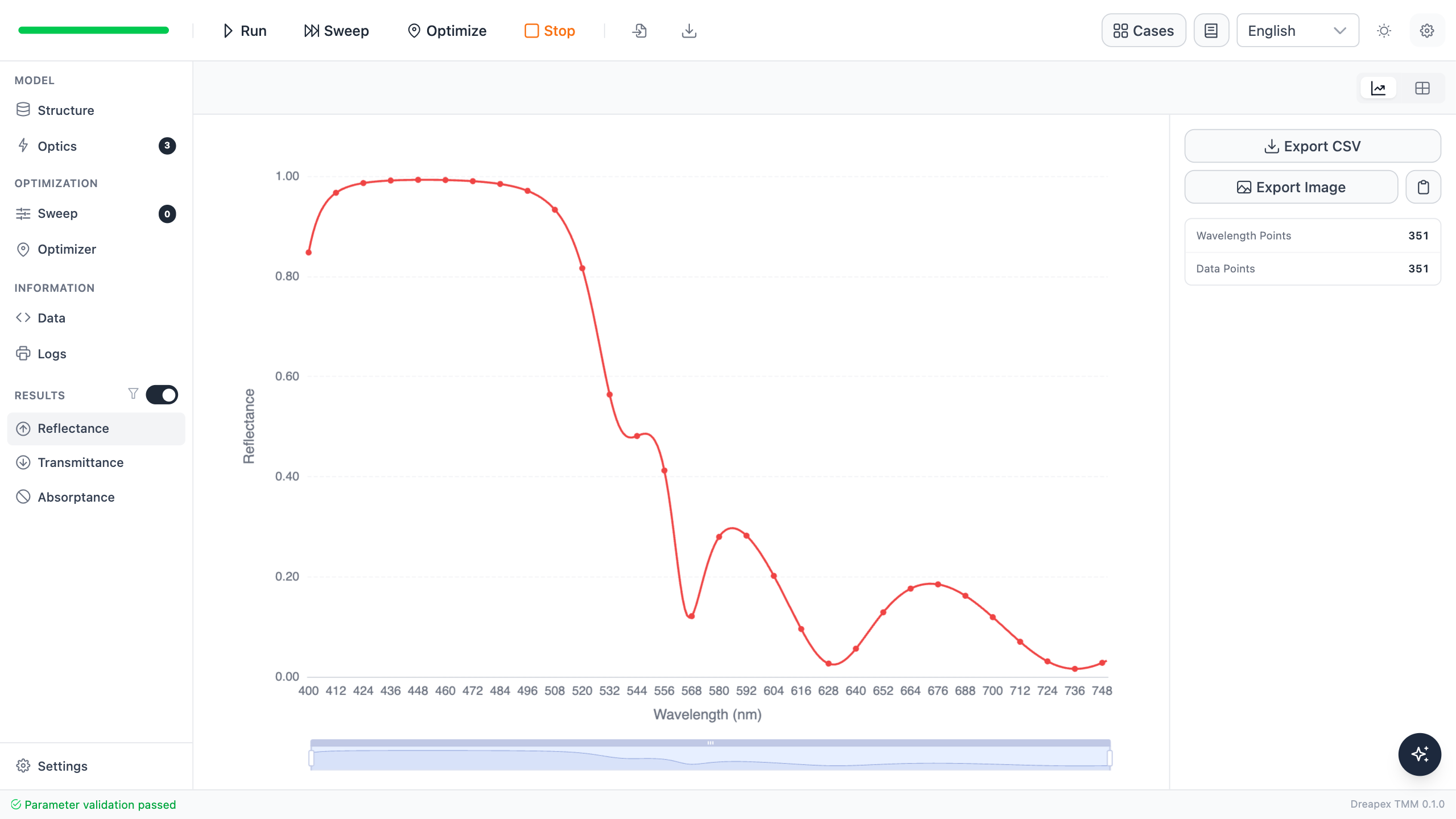
The eight-pair design raises mean blue-green reflectance to 96.332%, but mean red transmittance falls to 87.882%. More periods strengthen one target band while causing the other to miss the 90% specification.
Compare optical performance with structural cost
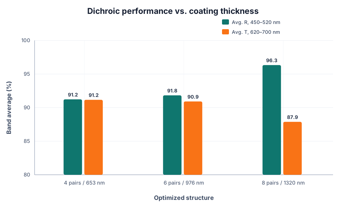
The combined chart places the two mean optical metrics beside total thickness. Both four and six pairs pass the dual-band mean-value specification, but the six-pair coating is about 49% thicker. Eight pairs are the thickest and miss the red-transmission requirement. Increasing pair count therefore does not by itself produce the better overall design.
A variable reaching a bound is not a calculation error. It indicates that, for the current objectives and structure, the optimizer would still prefer to decrease TiO₂ or increase MgF₂. If the bounds come from a real fabrication process, the appropriate response is to change the structural degrees of freedom or objective weights, not to ignore the bounds and compare objective-function values alone.
For all three lossless structures, the maximum energy-closure error is no greater than .
An unpolarized average does not replace polarization acceptance
Keep the incidence angle at 45° and set pRatio to 0 and 1 in turn to evaluate pure s and pure p polarization.
| Pair count | s: blue-green mean | p: blue-green mean | s: red mean | p: red mean |
|---|---|---|---|---|
| 4 | 97.720% | 84.737% | 86.559% | 95.762% |
| 6 | 98.820% | 84.828% | 84.763% | 97.067% |
| 8 | 99.806% | 92.857% | 82.437% | 93.327% |
Increasing the pair count improves some polarization metrics, but it does not improve all objectives simultaneously. If the specification requires every target wavelength to exceed a threshold for either polarization, evaluate each candidate by its minimum value and add s and p as separate optimization objectives.
Select the simplest structure that meets the specification
Under the specification used in this tutorial, the 4-pair structure keeps the mean values in both bands at or above 90%, uses the fewest layers and the smallest total thickness, and has no variables at their bounds. It is therefore the preferred design.
This conclusion applies only to the current materials, bands, angle, objective weights, and thickness ranges. If the blue-green mean reflectance must exceed 95%, the 8-pair candidate is closer to that target, but its insufficient red transmittance and bound-limited variables must be addressed again.
Variation Exercise
Build a five-pair stack from the common 56/100 nm starting point, keep the objectives, bounds, and algorithm unchanged, and optimize again. Insert the result into the 4/6/8-pair comparison table and determine whether the five-pair stack can pass both 90% mean-value specifications with less total thickness than the six-pair stack.
← Back to Tutorial Catalog · Next: Which Layer Absorbs the Light?