Separate Blue-Green and Red Light: Design a 45° Dichroic Beamsplitter
Fluorescence imaging, projection, and multispectral measurements often need to turn blue-green light arriving at 45° while allowing red light to continue forward. A dichroic beamsplitter is a stack of transparent thin films that uses interference to reflect one wavelength band and transmit another, rather than absorbing and discarding either beam.
This tutorial designs a dichroic beamsplitter that reflects blue-green light from 450–520 nm and transmits red light from 620–700 nm. You will build a periodic stack, set 45° incidence and dual-band optimization objectives, and evaluate the unpolarized, s-polarized, and p-polarized results separately.
| Band | Target | Validation quantity |
|---|---|---|
| 450–520 nm | Reflect blue-green | Maximize average reflectance |
| 521–619 nm | Allow the spectral transition | No objective |
| 620–700 nm | Transmit red | Maximize average transmittance |
Oblique Incidence Changes Optical Thickness
At 45° incidence, the propagation direction changes inside every layer. Reflections from adjacent interfaces travel different distances before recombining, so a thickness that works at normal incidence cannot simply be reused for an oblique-incidence design.
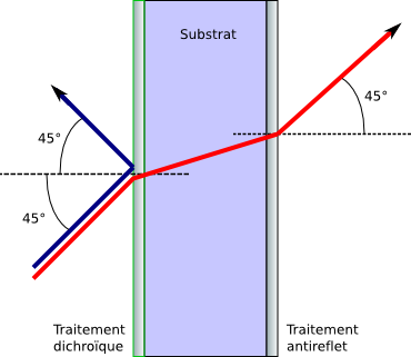
The left surface carries the dichroic coating and the right surface carries an antireflection coating. Blue light is reflected while red light passes through the substrate.
The propagation angle inside layer follows Snell's law:
Here, and are the refractive indices of the incident medium and layer ; is the external incidence angle; and is the refracted angle inside the layer. All angles are measured from the surface normal. The one-way phase thickness of that layer is
Here, is the phase thickness, is physical thickness, is the vacuum wavelength, and the other symbols retain their definitions above. As incidence angle increases, the change in shifts a normal-incidence quarter-wave condition. The s and p polarizations also have different interface reflection coefficients, so both must be checked for a 45° design.
Start from a Six-Pair Periodic Stack
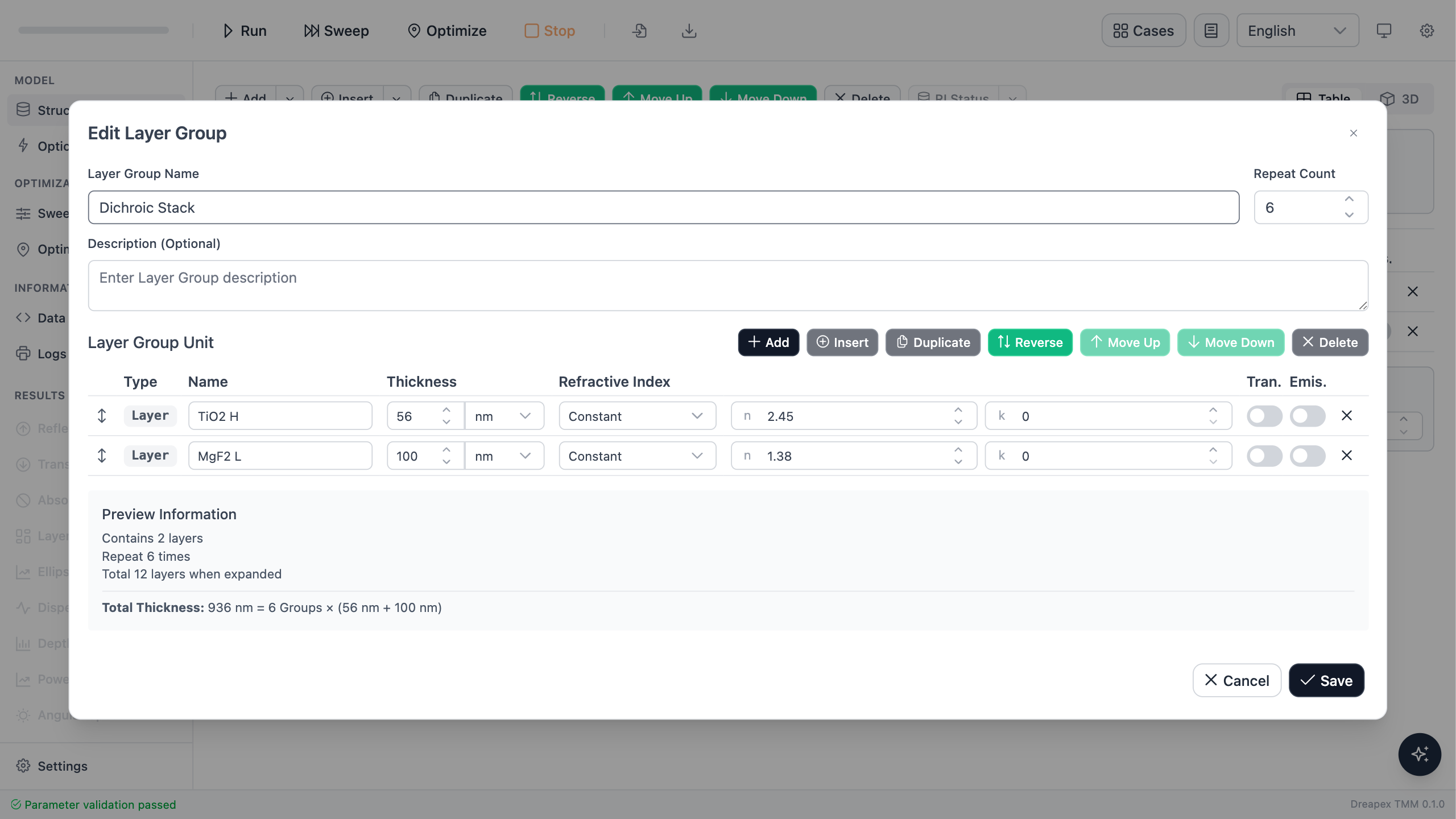
The initial structure is written as : the high-index layer H is 56 nm TiO₂, the low-index layer L is 100 nm MgF₂, and the complete period is repeated six times above a 1 mm incoherent glass substrate. Using only the two shared periodic thicknesses as variables exposes the trade-off between objectives without requiring twelve independent variables at once.
| Shared variable | Initial value | Allowed range |
|---|---|---|
| TiO₂ high-index layer | 56 nm | 25–80 nm |
| MgF₂ low-index layer | 100 nm | 70–140 nm |
Build the group with the initial 56/100 nm thicknesses and set Repeat Count to 6. Open Edit Group and verify the order, thicknesses, and repeat count.

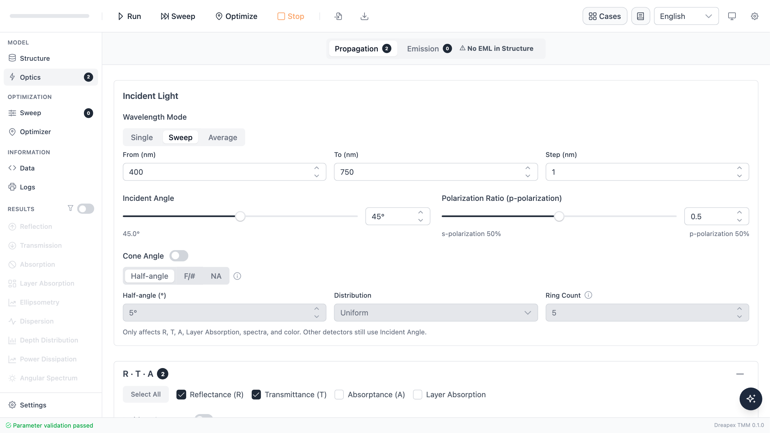
In Optics, set 400–750 nm with a 1 nm step, 45° incidence, and unpolarized light. The software represents the p-polarized fraction as pRatio: 0 is pure s, 1 is pure p, and 0.5 is an equal s/p average. Begin with 0.5 for unpolarized performance and enable Reflectance and Transmittance.
Run the Initial Stack First
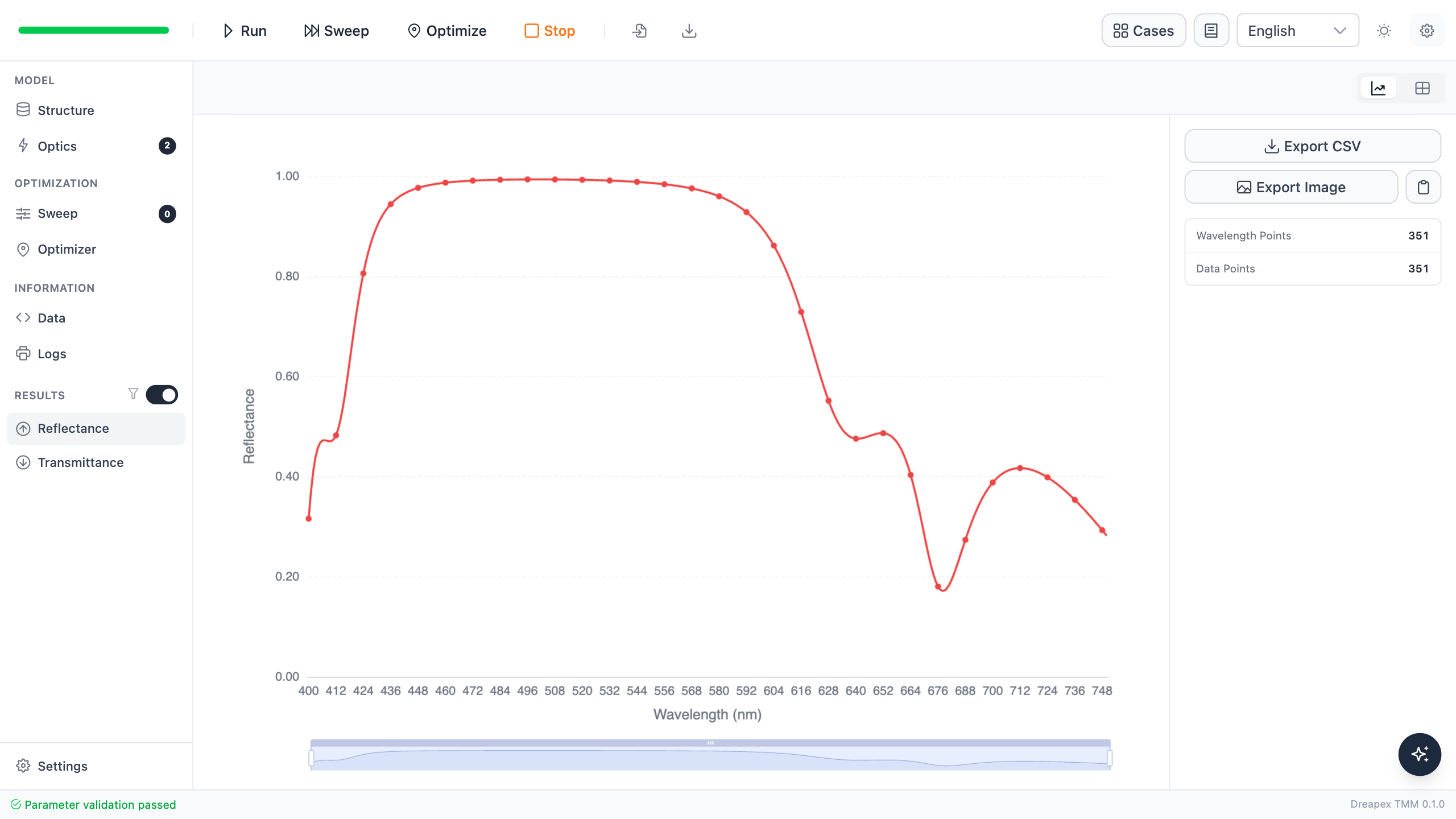
The initial 56/100 nm stack gives 99.084% average reflectance over 450–520 nm but only 59.676% average transmittance over 620–700 nm. Blue-green reflection is already strong; red transmission is the main design gap.
Translate the Specification into Two Objectives
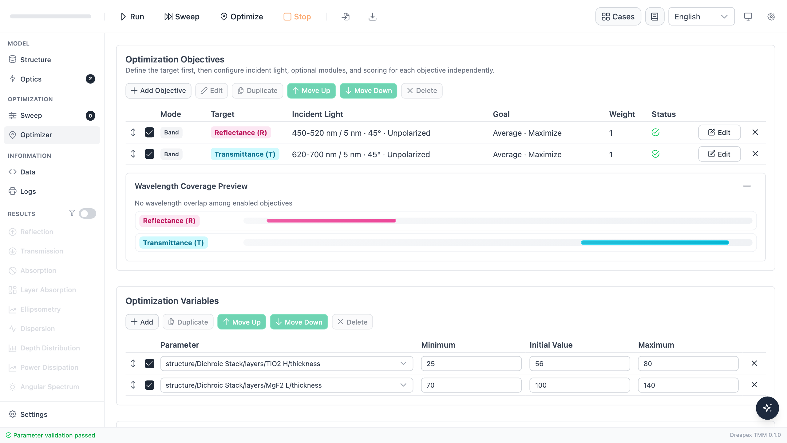
Add two equally weighted objectives in Optimizer:
- maximize average
Reflectancefrom 450 to 520 nm with a 5 nm step, at 45° with unpolarized light; - maximize average
Transmittancefrom 620 to 700 nm with a 5 nm step, at 45° with unpolarized light.
Both objectives must use the same angle and polarization definition. Otherwise, the optimizer would balance two different operating conditions, and the compromise would not correspond to one physical device use case.
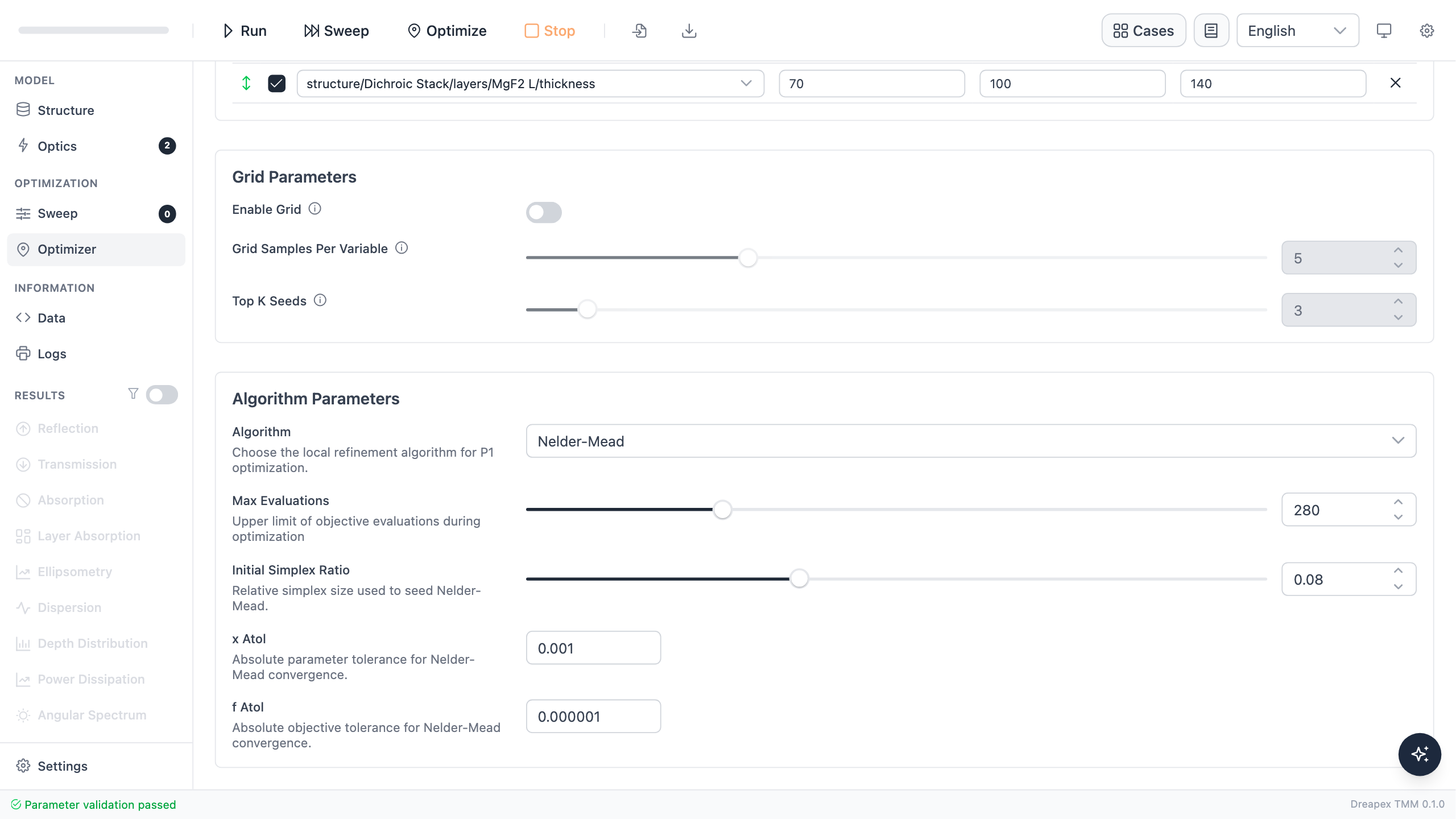
Choose Nelder–Mead, set 280 maximum evaluations, and use an initial simplex scale of 0.08. The real optimization converged after 102 objective evaluations. Its 5 nm sampled report gives 91.508% blue-green reflection and 90.678% red transmission. Apply the optimized thicknesses, then perform final validation with a finer 1 nm step.
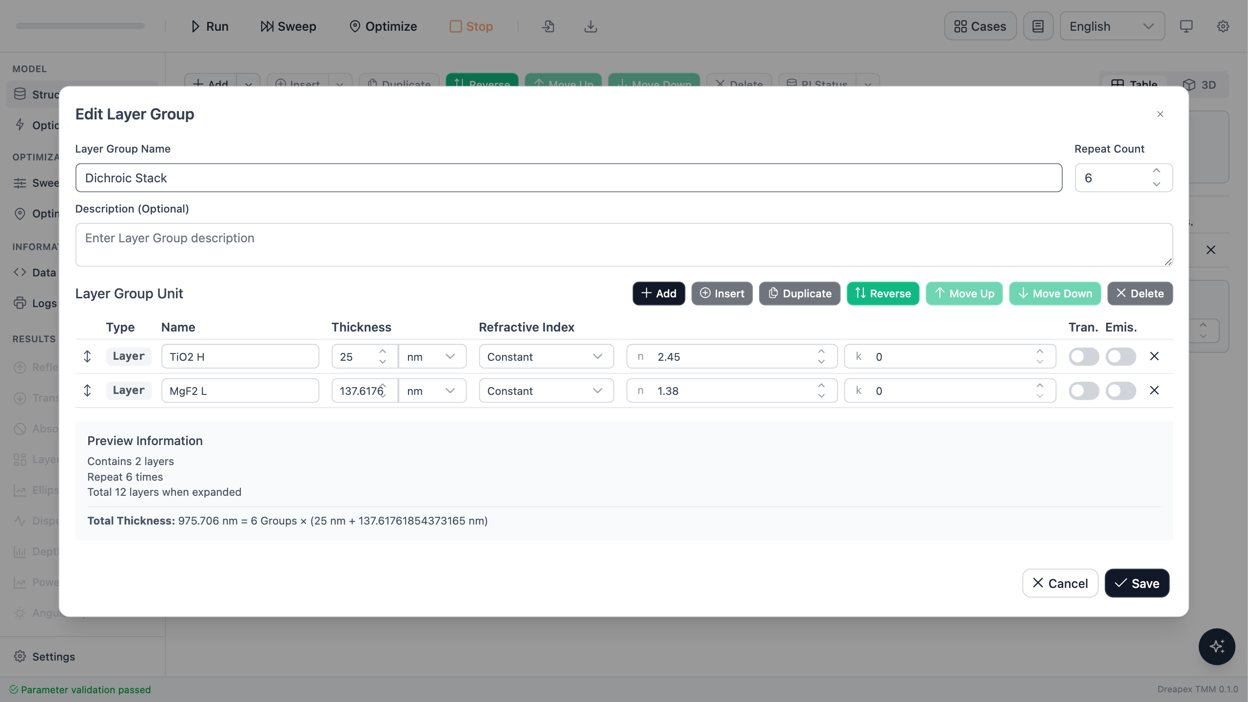
After optimization, select Apply to Structure, return to Structure, and confirm that the two group thicknesses were updated while Repeat Count remains 6.

Open Edit Group and confirm Repeat Count is 6, with 25.000 nm TiO₂ first and 137.618 nm MgF₂ second.
Unpolarized Result
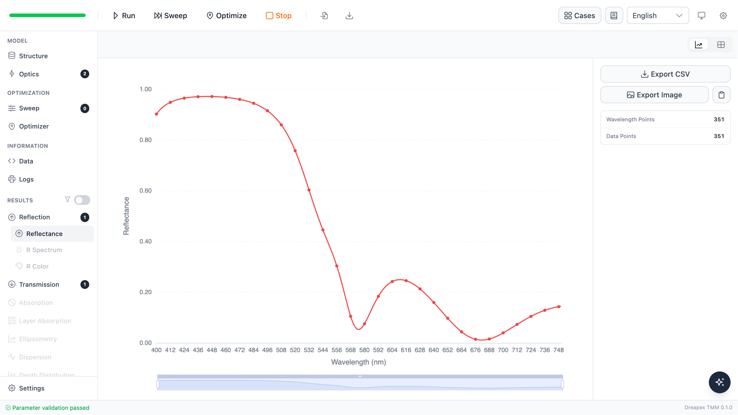
The 1 nm forward run gives 91.824% average reflectance over 450–520 nm, with a band minimum of 75.787% at 520 nm. Average transmittance over 620–700 nm is 90.915%, with a band minimum of 76.209% at 620 nm. Both minima occur at the edges nearest the transition region, consistent with a spectrum changing from reflection to transmission.
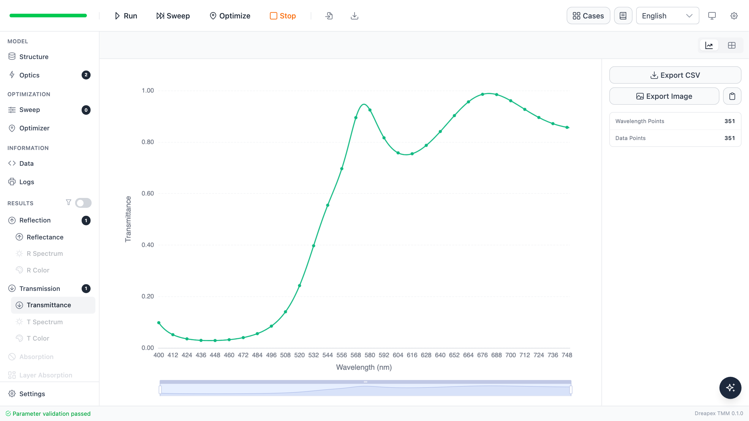
Optimization gives up some reflection margin to obtain much higher red transmission.
| Design | Average , 450–520 nm | Average , 620–700 nm | ||
|---|---|---|---|---|
| Initial 56/100 nm | 99.084% | 59.676% | — | — |
| Optimized 25.000/137.618 nm | 91.824% | 90.915% | 90.052% | 89.245% |
Validate s and p Separately
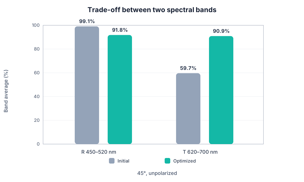
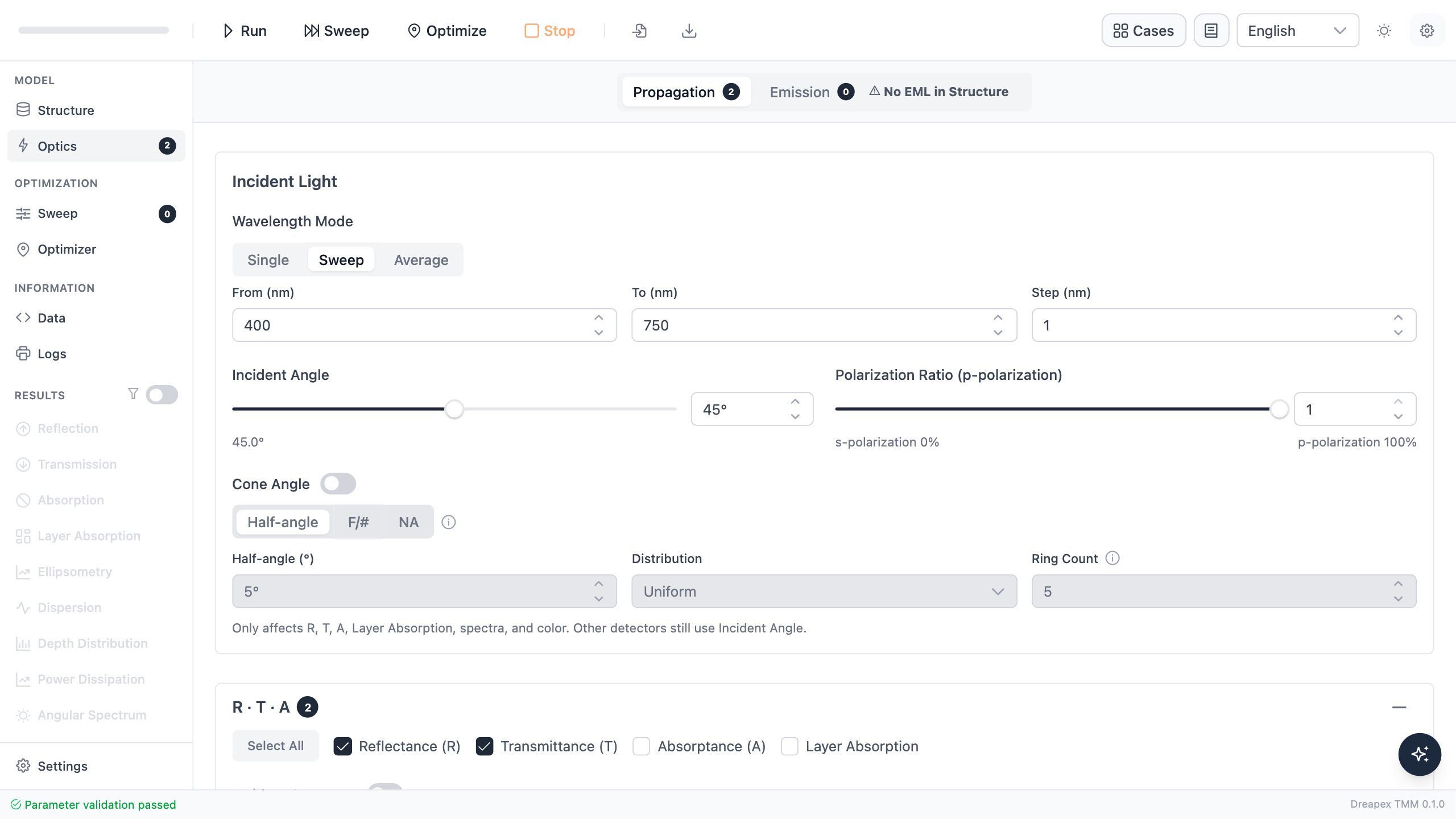
An unpolarized average can hide large differences between the polarizations. Keep the structure, wavelength range, and 45° incidence fixed; set pRatio to 0 and 1 in turn and run each case.
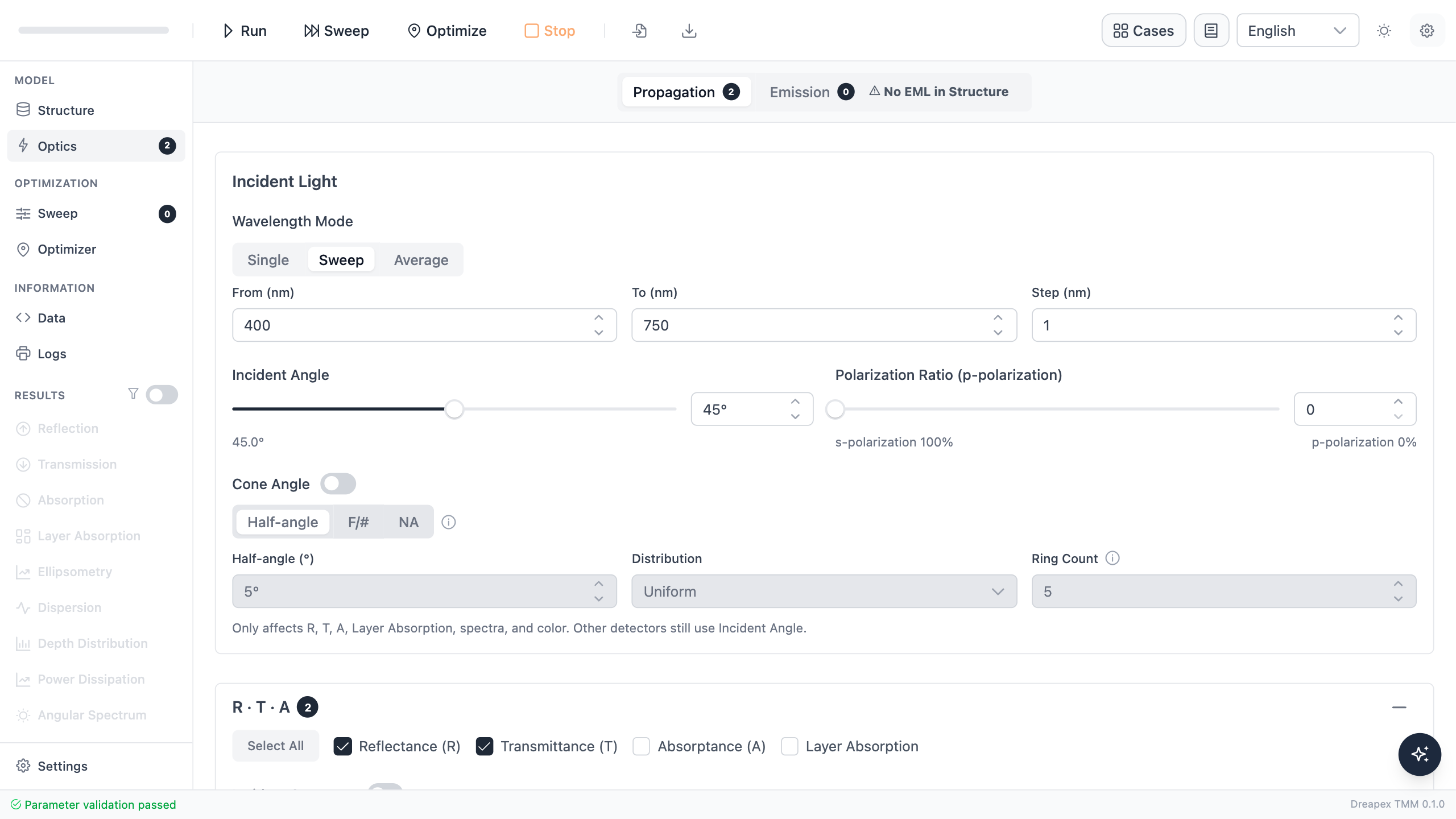
First set pRatio to 0, confirm that the interface shows 100% s polarization, and run the reflectance calculation.
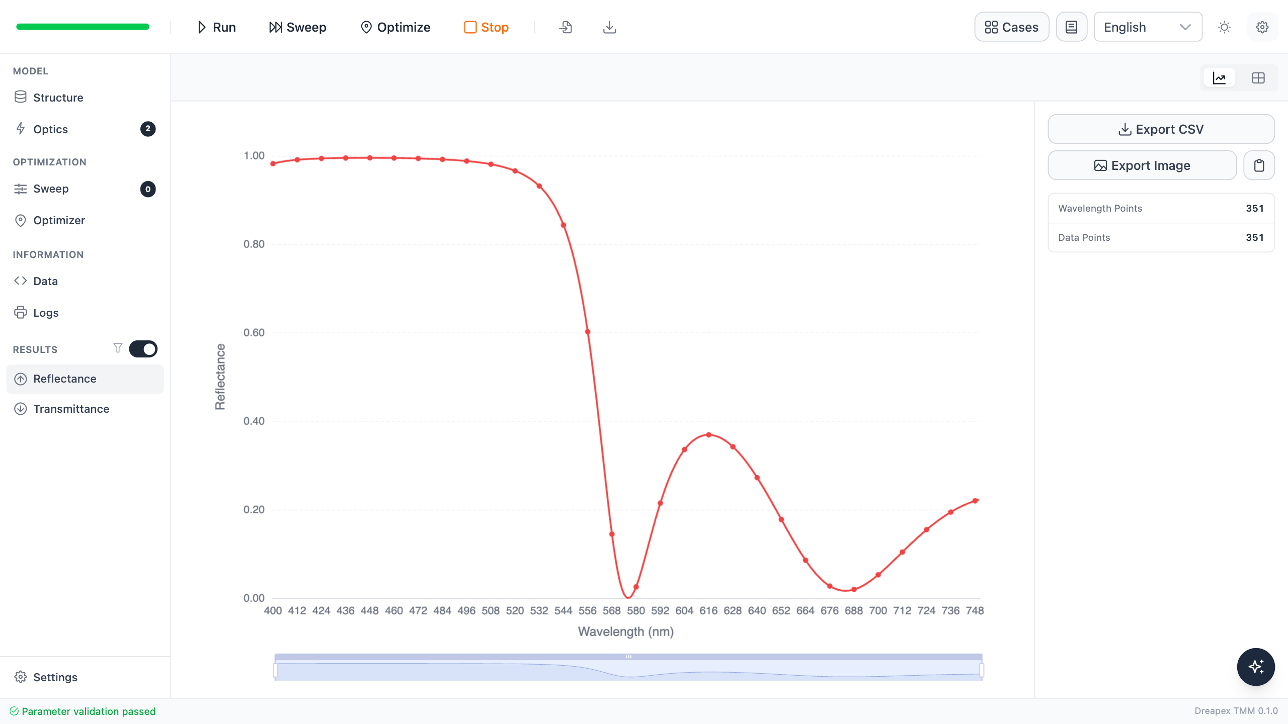
Then set pRatio to 1, confirm that the interface shows 100% p polarization, and rerun the same structure.
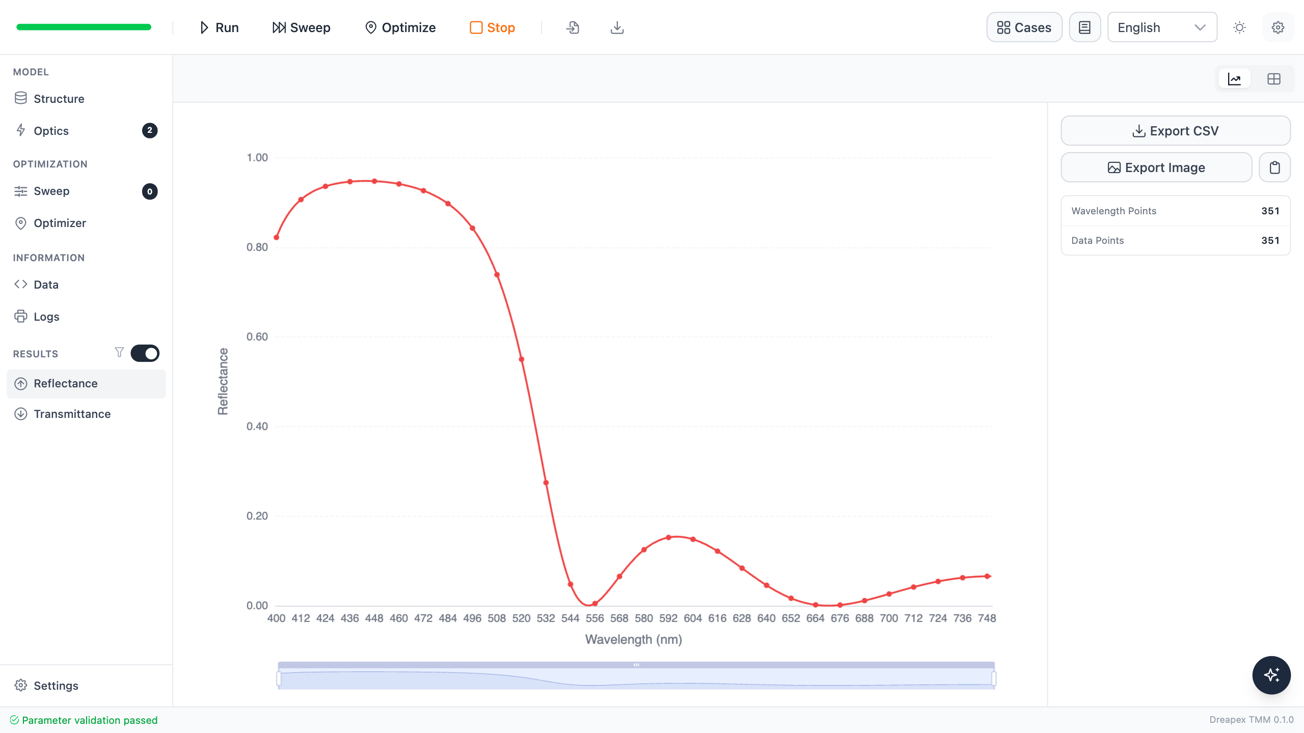
| Polarization | Average , 450–520 nm | Minimum in-band | Average , 620–700 nm |
|---|---|---|---|
| s | 98.820% | 96.568% | 84.763% |
| p | 84.828% | 55.005% | 97.067% |
| Unpolarized average | 91.824% | 75.787% | 90.915% |
The design meets this tutorial's unpolarized average objectives, but it is not a non-polarizing beamsplitter. The p-polarized blue-green response weakens strongly near the band edge, while s-polarized red transmission is below the unpolarized average. If an application requires both polarizations to meet the same threshold, add separate s and p objectives and allow more independent thickness variables.
The optimized TiO₂ thickness reaches its 25 nm lower bound. This tutorial only records that result; see Are More Layers Better? for the trade-off among variable bounds, pair count, and total thickness.
Variation Exercise
Keep the optimized structure and change only the incidence angle from 45° to 55°. Predict the change in the transition band and s/p separation, then run unpolarized, pure-s, and pure-p cases. Record which acceptance metric fails first.
For engineering work, repeat every acceptance calculation with real n and k dispersion, the intended substrate, deposition errors, and the actual angular distribution of the beam.