How Do Thickness Errors Shift a Filter? Fabry–Pérot Sensitivity Analysis
This tutorial continues Select One Color Between Two Mirrors: A Fabry–Pérot Narrowband Filter and reuses its symmetric 550 nm DBR–cavity–DBR structure.
A cavity error of only a few nanometers can shift a narrowband filter away from its target wavelength. This tutorial sweeps the Fabry–Pérot cavity thickness, quantifies changes in peak wavelength, full width at half maximum, and Q factor, and converts a spectral tolerance into a thickness tolerance.
Only the central MgF₂ cavity thickness changes in this tutorial. Both DBRs, all refractive indices, the incidence angle, and the wavelength sampling remain fixed, so any peak shift can be attributed directly to the cavity thickness.
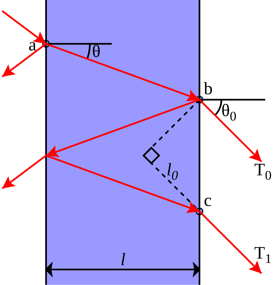
The Cavity and Mirrors Jointly Determine the Peak
At normal incidence, the round-trip phase condition inside the cavity is
Here, is the total round-trip phase, is the vacuum wavelength, and are the cavity refractive index and physical thickness, and are the reflection phases of the front and back DBRs, and is a positive integer resonance order. Phase is expressed in radians, and and use the same length unit.
If the reflection phases of the two DBRs are neglected, the first-order resonance simplifies to
The half-wave relation is useful for estimating the initial cavity thickness and correctly predicts that a thicker cavity shifts the peak toward longer wavelengths. Because DBR reflection phase varies with wavelength, however, the actual sensitivity must be calculated from the complete stack.
Fix the Mirrors and Optical Conditions
Reuse the 550 nm Fabry–Pérot filter:
| Region | Layer sequence | Repeats |
|---|---|---|
| Front mirror | MgF₂ 99.64 nm / TiO₂ 56.12 nm | 4 |
| Cavity | MgF₂ 199.28 nm | 1 |
| Back mirror | TiO₂ 56.12 nm / MgF₂ 99.64 nm | 4 |
| Substrate | 1 mm glass, incoherent | 1 |

The periodic sequences of the front and back mirrors are reversed. Open Edit Group for each mirror and confirm that both Repeat Count values are 4.
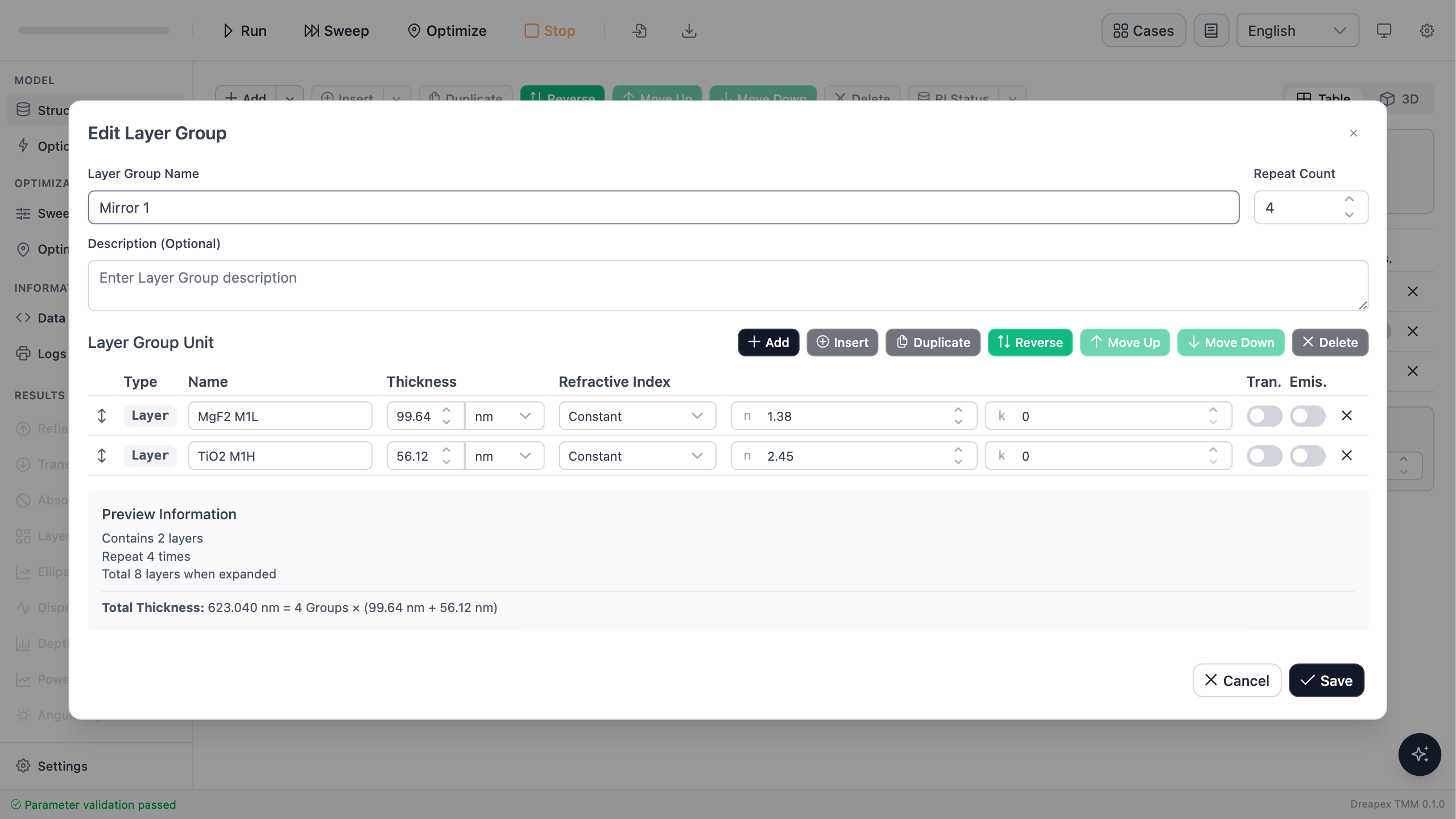

In Optics, set 450–700 nm with a 0.25 nm step, 0° incidence, and unpolarized light. Enable Reflectance, Transmittance, and Absorptance.

At the nominal cavity thickness of 199.28 nm, the transmission peak is at 550.00 nm, peak transmittance is 95.742%, and the full width at half maximum is 3.623 nm. A 1 nm wavelength step would leave only three or four samples across the peak and cannot locate the half-maximum crossings reliably.
The full width at half maximum (FWHM) and quality factor are defined as
Here, and are the wavelengths of the left and right crossings where transmittance falls to half its peak value, is the FWHM, is the peak wavelength, and is the dimensionless quality factor.
Sweep the Cavity Thickness
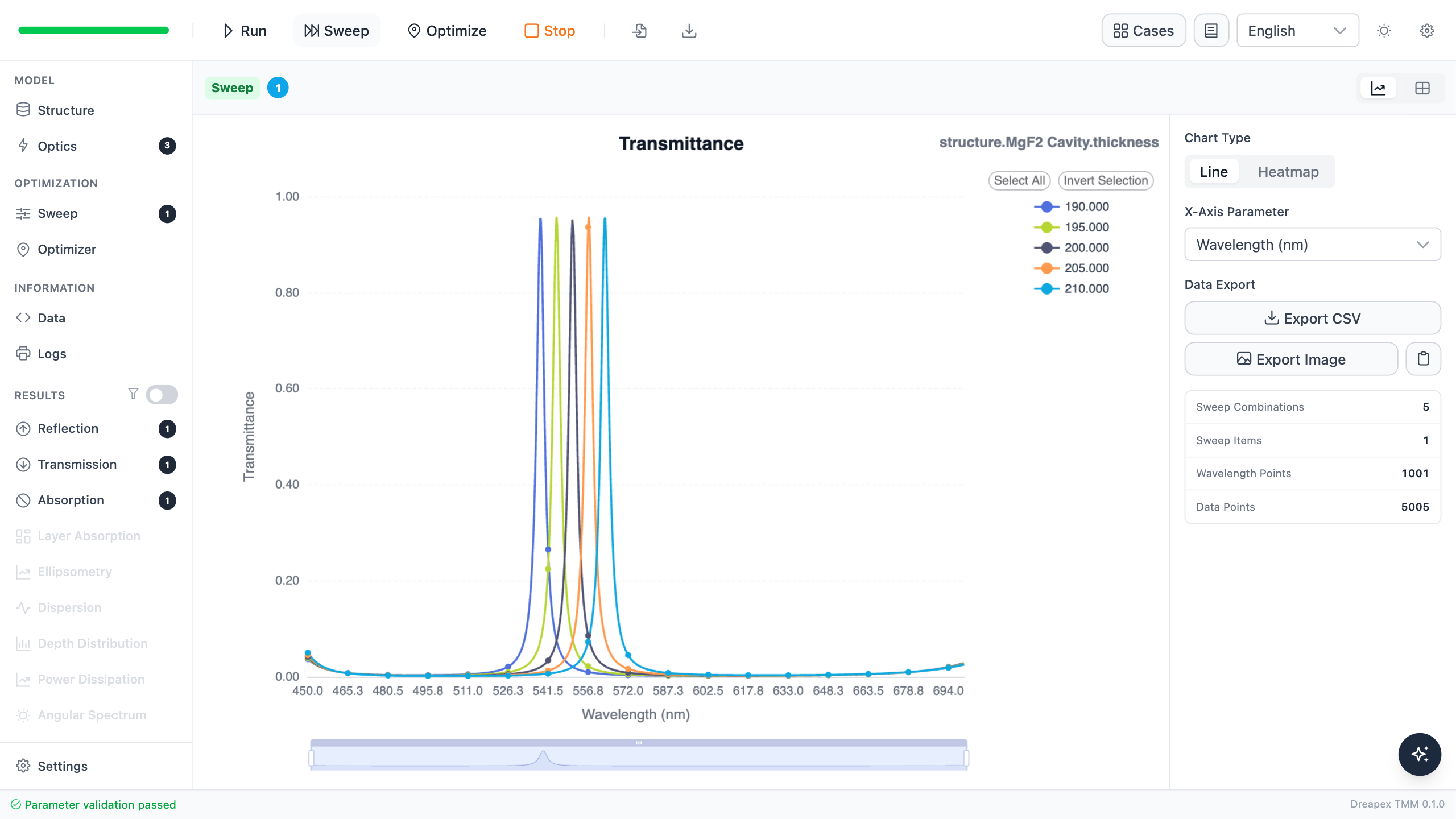
In Sweep, select MgF2 Cavity → Thickness and sweep from 190 nm to 210 nm in 5 nm steps.

After running the sweep, compare the five curves in Transmittance and track the same cavity mode within 500–600 nm.
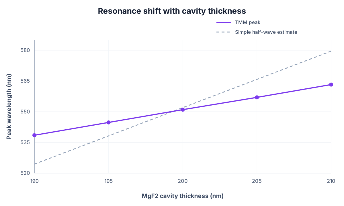
| Cavity thickness | Half-wave prediction | Simulated peak | Peak | FWHM | Q |
|---|---|---|---|---|---|
| 190 nm | 524.39 nm | 538.50 nm | 95.514% | 3.602 nm | 149.5 |
| 195 nm | 538.19 nm | 544.75 nm | 95.764% | 3.596 nm | 151.5 |
| 200 nm | 551.99 nm | 551.00 nm | 95.355% | 3.643 nm | 151.2 |
| 205 nm | 565.79 nm | 557.00 nm | 95.764% | 3.686 nm | 151.1 |
| 210 nm | 579.59 nm | 563.25 nm | 95.642% | 3.769 nm | 149.4 |
Increasing the cavity thickness by 20 nm shifts the transmission peak 24.75 nm toward longer wavelengths. Peak transmittance remains approximately 95.4%–95.8%, while FWHM stays between 3.60 nm and 3.77 nm. Over this range, cavity thickness primarily moves the peak without significantly degrading it.
The maximum energy-closure error across all sweep results is below .
Derive a Thickness Tolerance from Peak Drift
A linear fit to the five simulated points gives the local sensitivity around this design:
Here, is the local sensitivity of peak wavelength to cavity thickness; and are small changes in peak wavelength and cavity thickness, respectively. Near this design, a 1 nm change in cavity thickness moves the peak by approximately 1.24 nm.
The half-wave formula gives , more than twice the simulated value, because it neglects DBR reflection phase and effective penetration depth.
For an allowable peak-wavelength error , the cavity-thickness error can be estimated as
Here, is the cavity-thickness error, is the allowable peak-wavelength error, and is the local sensitivity defined above.
| Allowable peak error | Maximum cavity-thickness error |
|---|---|
| ±1 nm | approximately ±0.81 nm |
| ±2 nm | approximately ±1.62 nm |
| ±5 nm | approximately ±4.05 nm |
This is a deterministic, single-parameter sensitivity analysis, not a random-error or production-yield calculation. If the DBR pair count, materials, incidence angle, or operating wavelength changes, repeat the sweep and fit a new value of .
Design Decisions
| Design action | Main effect | Revalidate |
|---|---|---|
| Adjust cavity thickness | Moves the transmission peak | Peak wavelength and thickness tolerance |
| Add DBR pairs | Usually narrows the peak | Peak value, FWHM, Q, and absorption loss |
| Change incidence angle | Produces angular peak drift | Use angle and polarization |
| Use dispersive materials | Makes optical thickness wavelength dependent | Peak position and linewidth across the full band |
Hitting 550 nm in the nominal design is only the first step. A manufacturable filter must also convert the spectral specification into a thickness specification and confirm that the deposition process can meet it.
Variation Exercise
Change the cavity-thickness sweep to 195–203 nm with a 1 nm step and leave all other settings unchanged. Fit again near the nominal thickness and compare the fine-sweep result with the five-point value of 1.235 nm/nm obtained above.
← Back to Tutorial Catalog · Next: Split One Beam into Equal Halves