Select One Color Between Two Mirrors: A Fabry–Pérot Narrowband Filter
Two high-reflecting mirrors placed together seem as though they should block even more light. Yet when the round-trip phase between them is just right, the transmitted waves interfere constructively and open a very narrow transmission peak inside the high-reflectance band. A Fabry–Pérot narrowband filter uses this effect to select a specific color.
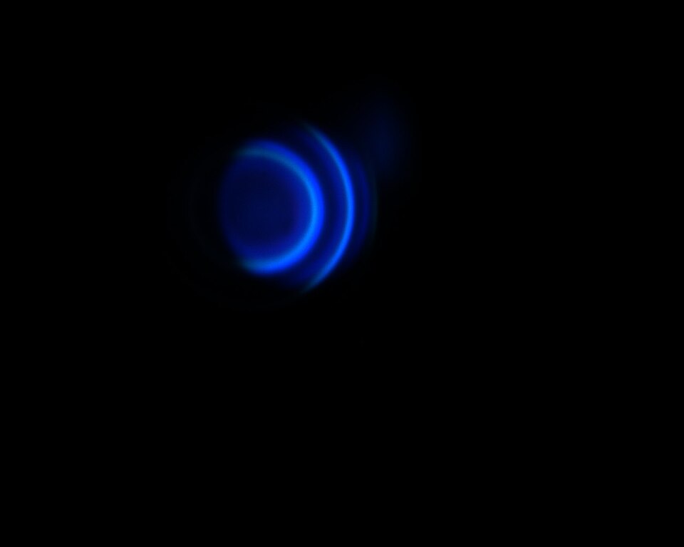
This tutorial builds that transmission peak near 550 nm. You will calculate the cavity thickness, configure two mirror-symmetric DBRs, and evaluate the filter using peak transmittance, full width at half maximum (FWHM), and Q factor.
The Half-Wave Cavity Condition
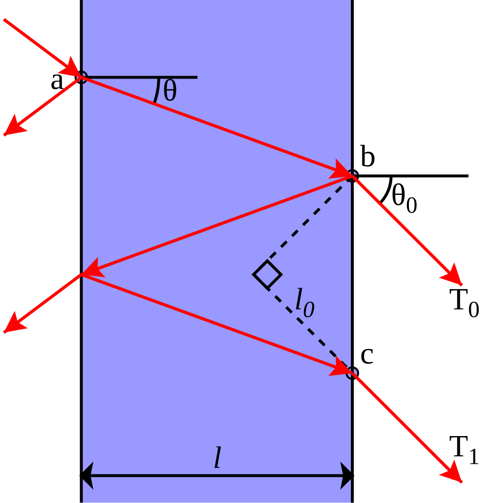
The red rays show the transmitted beams produced after repeated round trips between the two reflecting interfaces; is the propagation angle inside the cavity. The derivation below begins with the normal-incidence resonance condition.
At normal incidence, the basic cavity resonance condition is
Here, is the cavity refractive index, is its physical thickness, is a positive integer resonance order, and is the vacuum resonance wavelength. For an MgF₂ cavity with , , and ,
This is a half-wave optical thickness. The DBRs add reflection phase, but for this symmetric quarter-wave construction, 199.28 nm places the transmission peak exactly at 550 nm.
Mirror-Symmetric Layer Order
Build the following structure from air to the glass substrate:
| Region | Layer order | Repeats |
|---|---|---|
| Front mirror | MgF₂ 99.64 nm / TiO₂ 56.12 nm | 4 |
| Cavity | MgF₂ 199.28 nm | 1 |
| Back mirror | TiO₂ 56.12 nm / MgF₂ 99.64 nm | 4 |
| Substrate | Glass, 1 mm and incoherent | 1 |
The front mirror starts with low index and ends with high index. The back mirror starts with high index and ends with low index. Both cavity-facing layers are TiO₂, making the complete stack mirror-symmetric about the cavity center.

Click Edit Group for the front mirror. Confirm MgF₂ 99.64 nm → TiO₂ 56.12 nm with Repeat Count set to 4.

Open Edit Group for the back mirror. Confirm the reversed order, TiO₂ 56.12 nm → MgF₂ 99.64 nm, with Repeat Count also set to 4.

Use a Fine Wavelength Step
In Optics, set 450–700 nm with a 0.25 nm step, 0° incidence, unpolarized light, and enable Reflectance and Transmittance. The 1 nm step used for the DBR can only outline this approximately 3.6 nm-wide peak. A 0.25 nm step provides better estimates of the peak and full width at half maximum.

Run and Identify the Cavity Mode
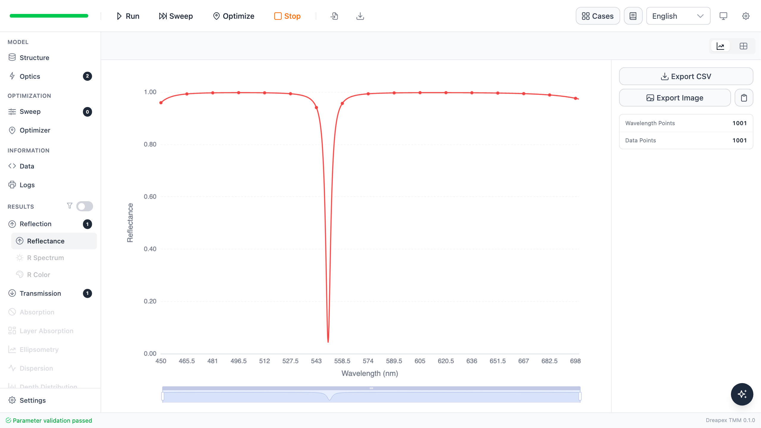
The broad DBR stopband remains in the reflectance result, but a narrow reflectance minimum appears near 550 nm. It is not a mirror failure: cavity resonance transfers the energy to the transmitted side.
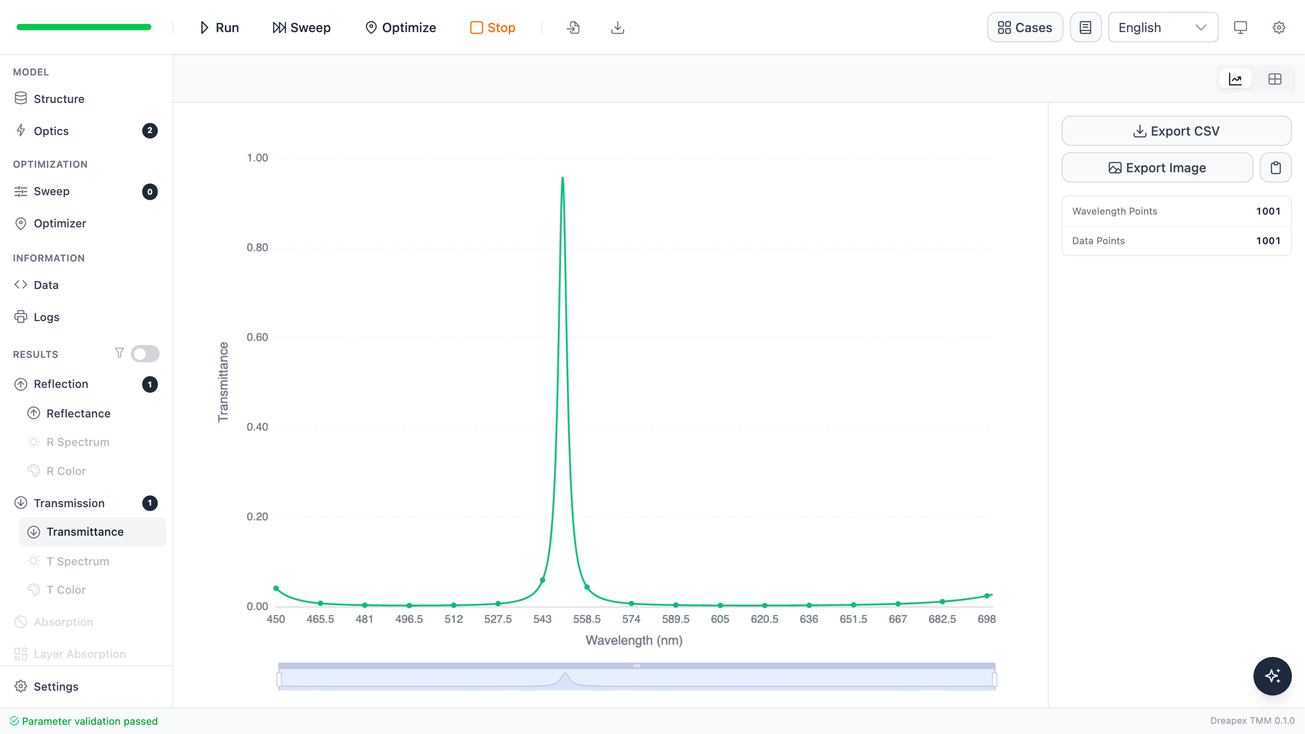
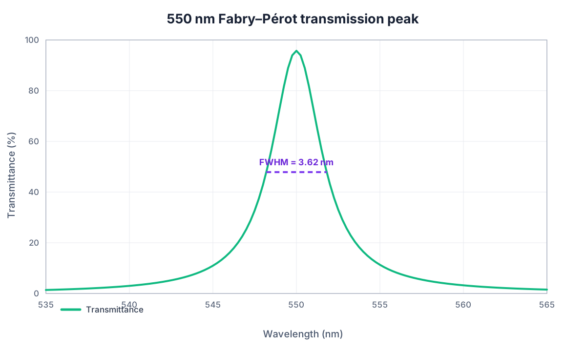
Transmittance reaches 95.742% at 550.00 nm. With zero absorption, the reflectance minimum and transmission maximum are complementary and still satisfy .
Validate with FWHM and Q Factor
The full width at half maximum (FWHM) is the wavelength separation between the two points where transmittance falls to half its peak value. Linear interpolation between adjacent samples gives a left crossing at 548.194 nm and a right crossing at 551.817 nm, so
Here, is the FWHM, while and are the left and right half-maximum wavelengths. The quality factor is
where is dimensionless, is the peak wavelength, and is the FWHM above. A higher means a narrower peak relative to its center wavelength.
| Metric | Result | Tutorial criterion |
|---|---|---|
| Peak wavelength | 550.00 nm | Matches the design wavelength |
| Peak transmittance | 95.742% | High transmission of the target color |
| FWHM | 3.623 nm | Narrowband selection is present |
| Q factor | 151.8 | Consistent with the measured linewidth |
Variation Exercise
Change only the MgF₂ cavity thickness from 199.28 nm to 205 nm. Predict whether the transmission peak moves to a shorter or longer wavelength, then run and record its position. The next tutorial, Fabry–Pérot Sensitivity Analysis, converts this shift into a thickness tolerance.
A practical narrowband filter also requires checks of angular peak shift, material absorption, and mirror asymmetry.
← Back to Tutorial Catalog · Next: How Do Thickness Errors Shift a Filter?