A Mirror Made of Transparent Materials: Design a 99% DBR
Transparent materials can form a mirror with more than 99% reflectance. A distributed Bragg reflector (DBR) alternates transparent high- and low-index layers. Reflections from their interfaces return in phase near the design wavelength, creating a high-reflectance stopband. DBRs are widely used in laser mirrors, narrowband filters, and optical cavities.
This tutorial builds a five-pair MgF₂/TiO₂ DBR. You will calculate quarter-wave thicknesses, create the periodic stack with Layer Group, and verify the design through its reflectance spectrum and pair-count dependence.
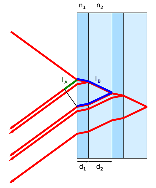
DBR Operating Principle
The diagram represents a dielectric mirror made from alternating layers with indices and . Each interface returns a weak reflection. With the right layer thicknesses, these reflected waves return in phase and reinforce one another.

The Quarter-Wave Period
Keep the design wavelength at . The physical quarter-wave thickness of each layer is
Here, is the physical thickness of material , is its refractive index, and is the vacuum design wavelength. With and , the high-index TiO₂ layer is and the low-index MgF₂ layer is .
Use the order from the air side, meaning TiO₂ followed by MgF₂ and repeated times. At the design wavelength, the main reflected components from the interfaces return with nearly the same phase. The ideal quarter-wave center reflectance is
Here, is the power reflectance at ; and are the indices of air and the glass substrate; and are the high- and low-index material indices; and is the number of layer pairs. Because is greater than 1, the exponent drives reflectance rapidly toward unity.
Build a Five-Pair DBR
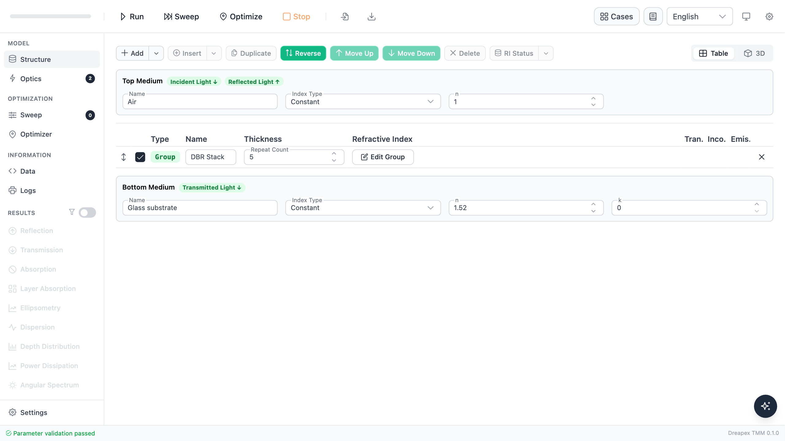
Add a Layer Group in Structure. Put 56.12 nm TiO₂ first and 99.64 nm MgF₂ second, then set Repeat Count to 5. Place a 1 mm incoherent glass substrate under the group and set the bottom medium index to 1.52.
Click Edit Group to open the periodic unit. Confirm that the first layer is 56.12 nm TiO₂, the second is 99.64 nm MgF₂, and Repeat Count is 5.
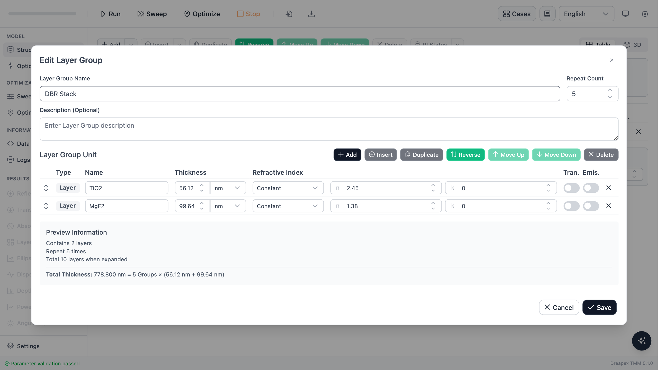
The Layer Group stores the period once. To compare through , edit only Repeat Count rather than manually copying and deleting ten individual layers.
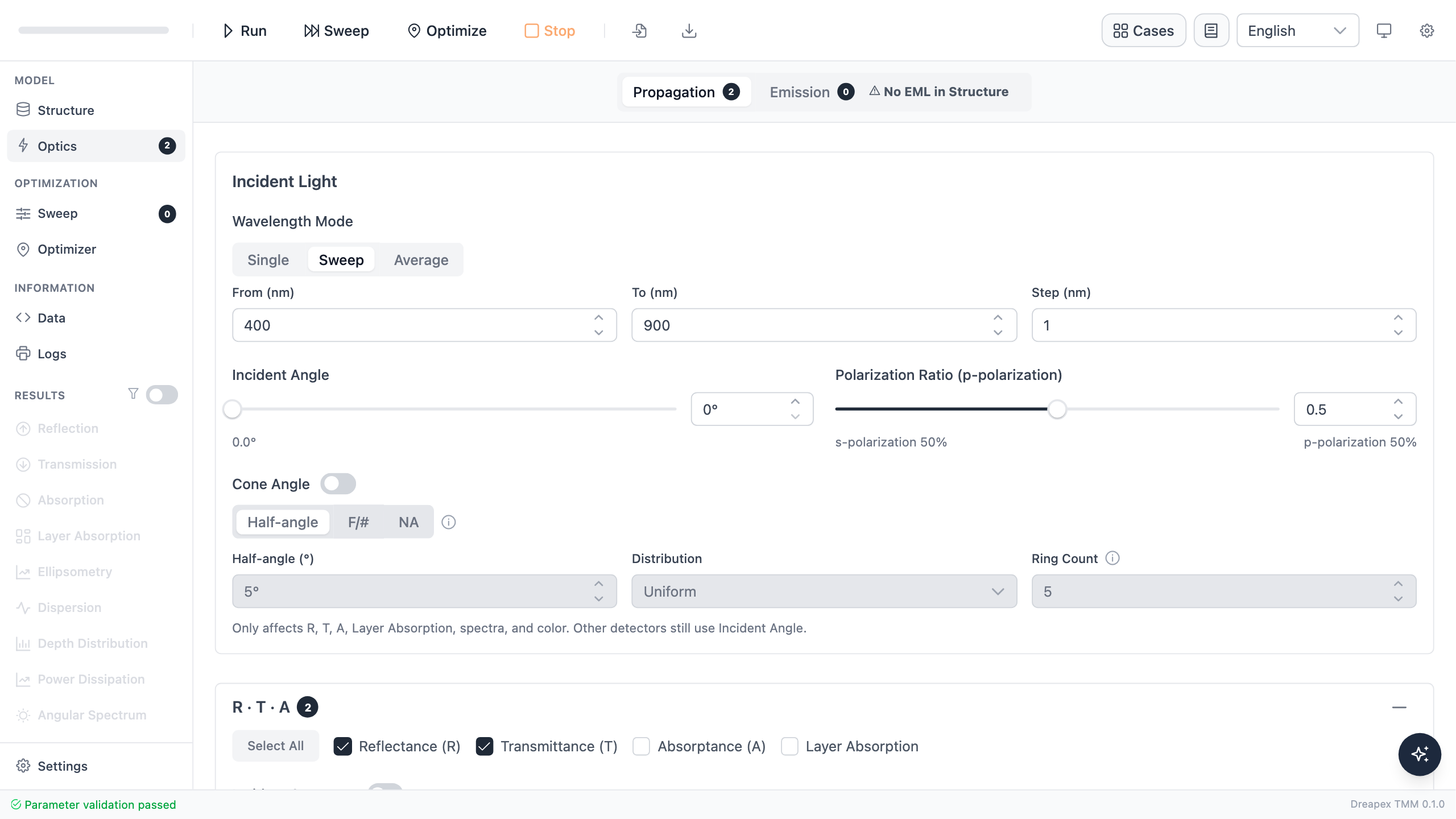
In Optics, set 400–900 nm with a 1 nm step, 0° incidence, unpolarized light, and enable Reflectance and Transmittance. The broad wavelength range reveals both the central stopband and the transmission regions on its sides.
Before running, make a prediction: the five-pair stack should form a continuous high-reflectance band near 550 nm. A fifth pair should still raise center reflectance, but by less than the first few added pairs.
Run and Identify the Stopband
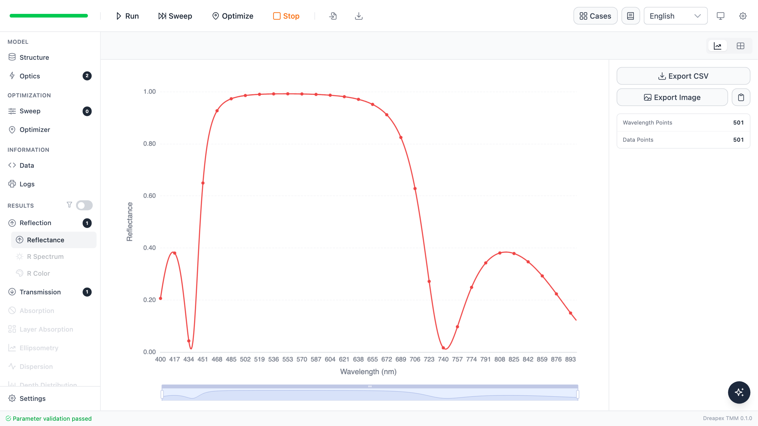
The five-pair structure reaches 99.158% reflectance at 550 nm. Using as the high-reflectance criterion for this tutorial gives a continuous stopband from 523 to 580 nm. The design wavelength lies inside this band, but the shape need not be perfectly symmetric about 550 nm because the incident medium and glass substrate have different indices.
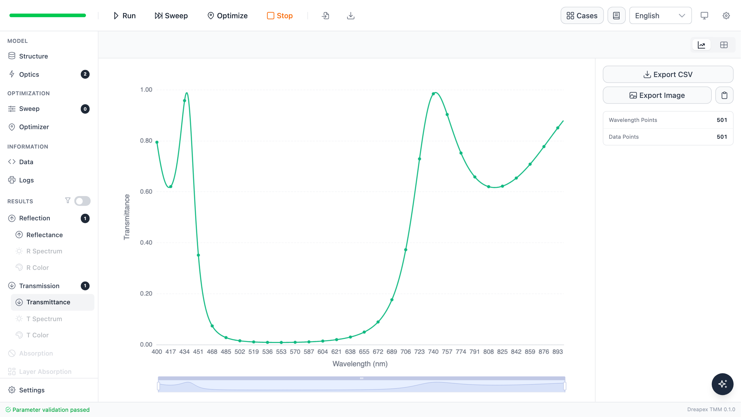
Transmittance falls over the same band. All materials are lossless, so every wavelength should satisfy ; the maximum numerical error in this run is about .
Change the Pair Count
Set Repeat Count to 1, 2, 3, 4, and 5 in turn, running the calculation and recording reflectance at 550 nm each time. Keep all other settings fixed so that changes in the curve can be attributed to pair count alone.
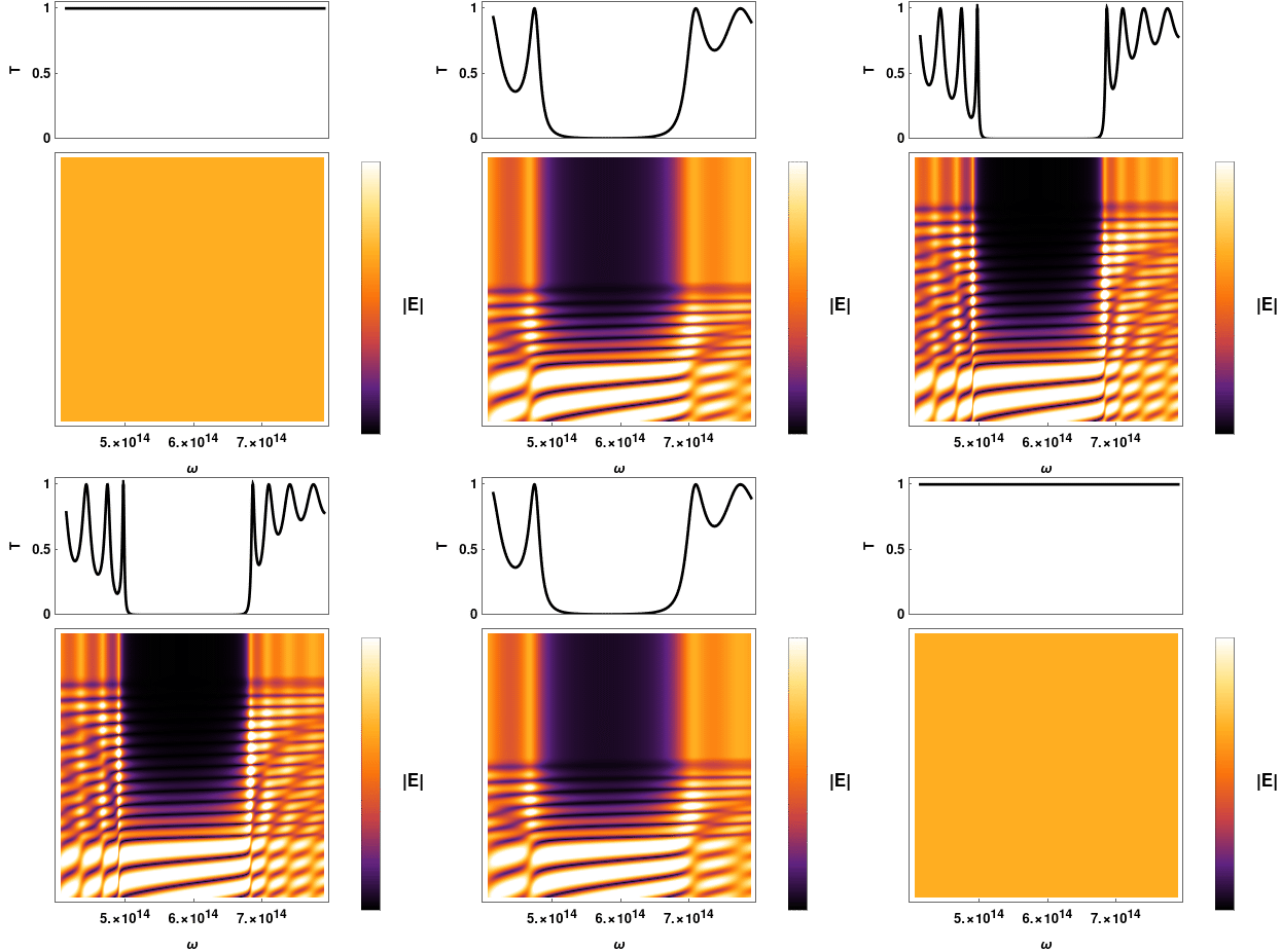
The animation shows the transmission stopband and internal electric field emerging as dielectric layers are added. The upper panel is transmittance and the lower panel is field magnitude; the low-transmission band becomes more pronounced as the stack grows.
Original animation and license

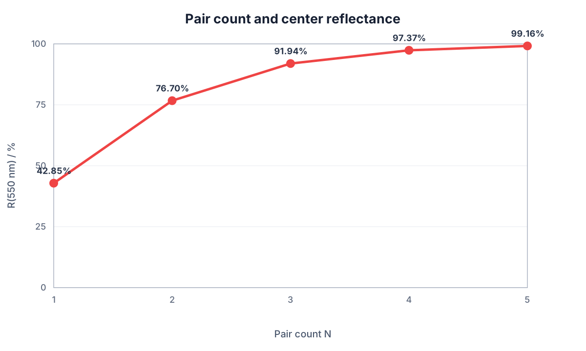
| Pair count | Reflectance at 550 nm |
|---|---|
| 1 | 42.854% |
| 2 | 76.699% |
| 3 | 91.938% |
| 4 | 97.369% |
| 5 | 99.158% |
The results show two design rules. Additional pairs raise center reflectance substantially, but with diminishing returns. High reflectance at one wavelength also does not guarantee a sufficiently wide stopband; a device specification must state both a reflectance threshold and a wavelength range.
Variation Exercise
Change only Repeat Count from 5 to 6. Estimate the remaining increase at 550 nm before running, then record the new center reflectance and the band. Decide whether two more layers deliver a comparable gain.
A practical DBR also requires dispersive material data, angle and polarization checks, and thickness-error analysis.
← Back to Tutorial Catalog · Next: Fabry–Pérot Narrowband Filter