How Do Ψ and Δ Reveal Thin-Film Changes? An Introduction to Ellipsometry
The reflectance change from a transparent film can be small even when the polarization of the reflected light has changed substantially. Ellipsometry uses that change: Ψ and Δ jointly measure the amplitude ratio and phase difference between p- and s-polarized reflection.
This tutorial builds a first ellipsometry model for an air / SiO₂ / Si structure, then sweeps the SiO₂ thickness from 50 to 150 nm. By the end, you can configure an ellipsometry calculation, read Ψ/Δ spectra, and identify spectral regions that are more sensitive to film thickness.
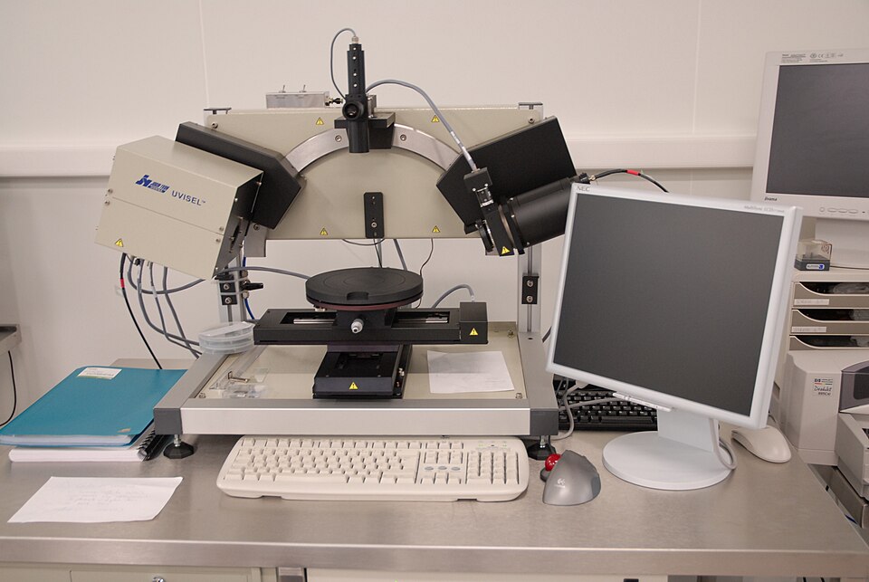
Definition of Ψ and Δ
Incident light can be resolved into p polarization parallel to the plane of incidence and s polarization perpendicular to it. Let and be their complex amplitude reflection coefficients. The ellipsometric ratio is
Here, is the complex ellipsometric ratio; and are the complex amplitude reflection coefficients for p and s polarization; describes their amplitude ratio; describes their phase difference; and is the imaginary unit. Ψ and Δ must be used together to describe the change in the polarization ellipse completely.
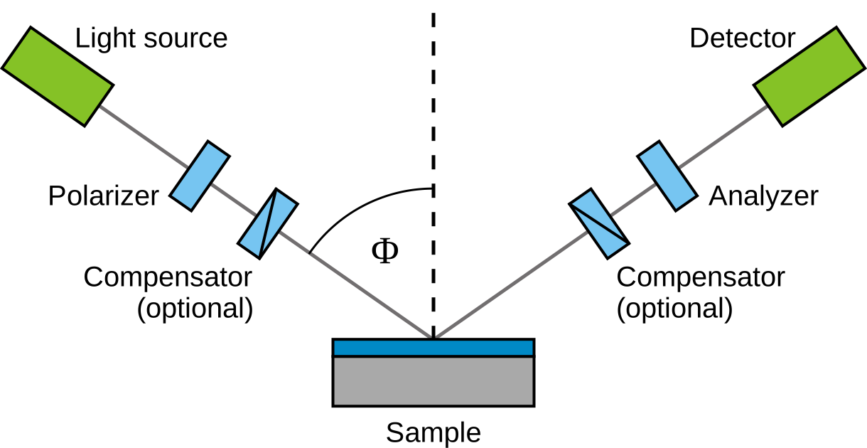
Ellipsometry is normally performed at oblique incidence, where the p and s reflection responses differ more strongly. A change in film thickness or refractive index changes the optical phase thickness, shifting or reshaping the Ψ and Δ spectra.
Build the SiO₂ / Si Model
Create an air / SiO₂ / Si structure. Use wavelength-dependent optical constants for a 100 nm SiO₂ film. Treat silicon as the semi-infinite bottom medium rather than adding a millimeter-scale coherent film.
| Position | Material | Setting |
|---|---|---|
| Top medium | Air | , |
| Film | SiO₂ | 100 nm, wavelength-dependent index |
| Bottom medium | Si | Wavelength-dependent complex index |

Configure Oblique-Incidence Ellipsometry
On the Optics page, use 400–800 nm with a 2 nm step and an incidence angle of 70°. Enable Psi and Delta. The ellipsometric parameters are calculated from the ratio of p and s reflection coefficients; pRatio is not an experimental polarizer angle that needs to be swept.

Read Ψ and Δ for the 100 nm Film
Run the calculation and open Psi first.
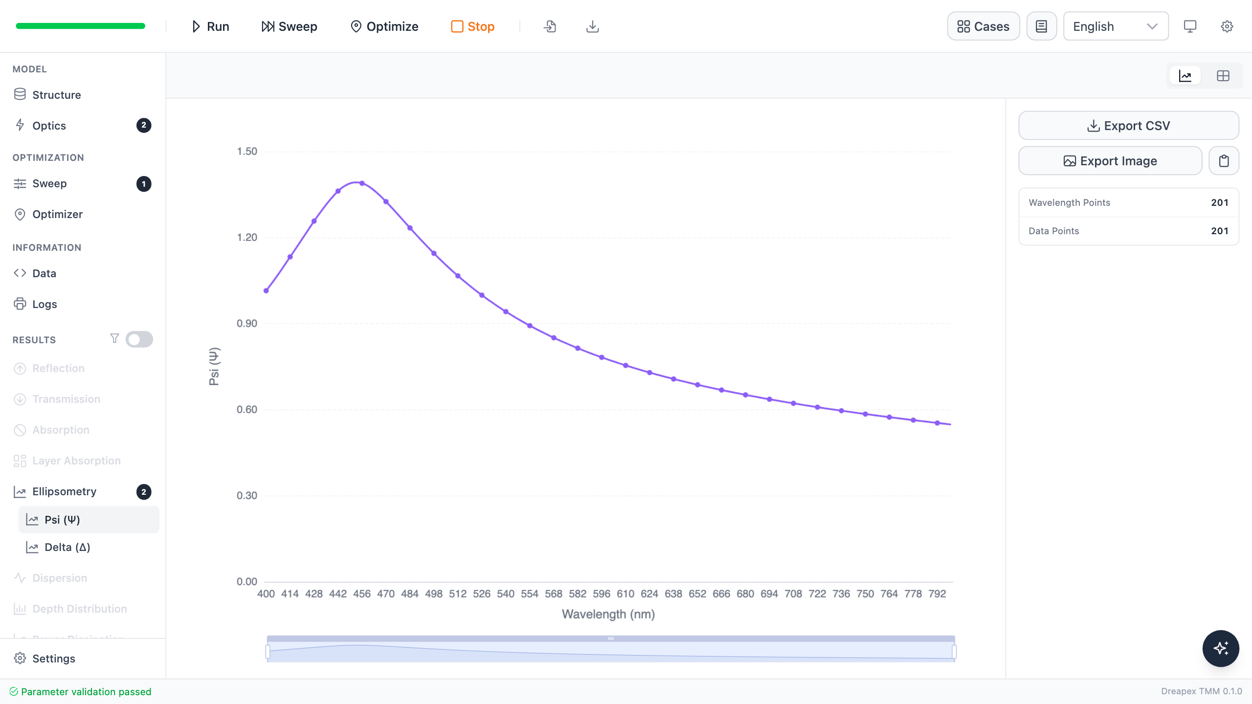
Ψ describes the changing ratio of p and s reflection amplitudes. At 550 nm, Ψ is about 0.906 rad (51.90°) for the 100 nm film. The spectral shape combines thin-film interference with the complex refractive index of silicon.
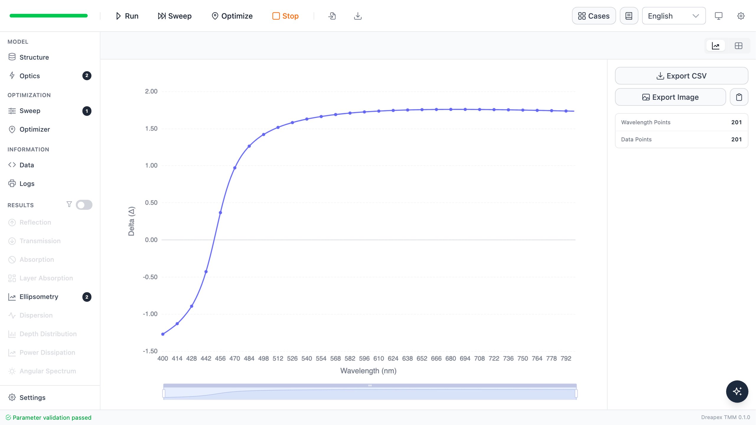
Δ is the phase difference between p and s reflection. At 550 nm, it is about 1.653 rad (94.70°). The result page displays phase in a principal range. When a curve crosses the boundary it may jump from a positive to a negative value; this is phase wrapping, not a physical discontinuity in the sample response.
Sweep Thickness and Watch the Spectra Move
On the Sweep page, add SiO2 Film → Thickness from 50 to 150 nm with a 25 nm step.

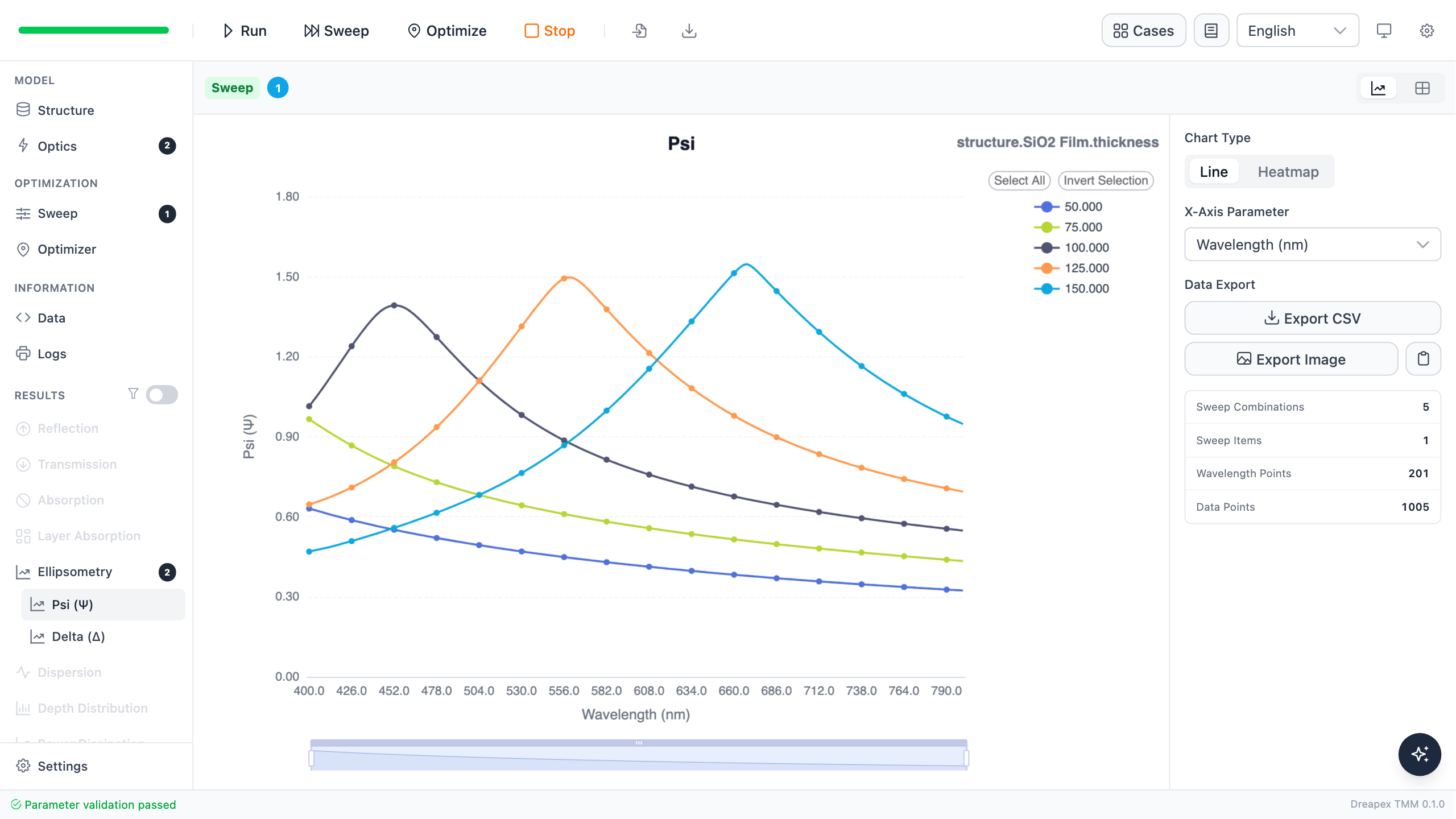
As thickness increases from 50 to 150 nm, the Ψ maximum moves progressively toward longer wavelengths. The curves do not simply shift vertically: both peak position and line shape change, so a full spectrum contains more thickness information than one wavelength.
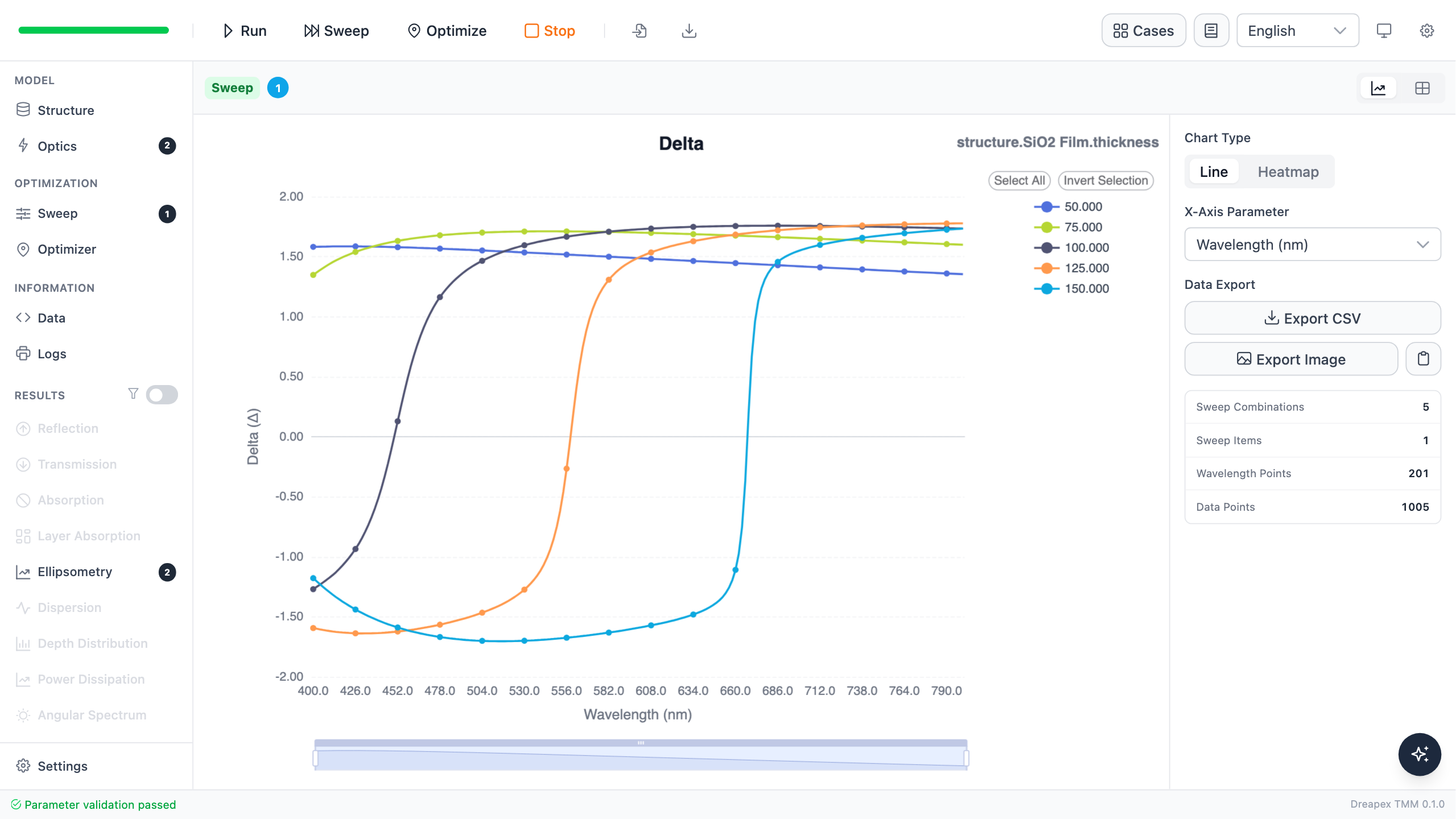
Δ is also sensitive to thickness, and the location of phase wrapping moves with the film. When comparing or fitting curves, use a consistent phase representation rather than interpreting jumps between -equivalent values as large errors.
At 550 nm, the results are:
| SiO₂ thickness | Ψ | Δ |
|---|---|---|
| 50 nm | 25.98° | 87.17° |
| 75 nm | 35.37° | 98.02° |
| 100 nm | 51.90° | 94.70° |
| 125 nm | 83.94° | −42.83° |
| 150 nm | 48.22° | −96.36° |
The negative Δ values for 125 and 150 nm follow from the selected principal range. Their equivalent unwrapped values are 317.17° and 263.64°.
From a Forward Model to Thickness Measurement
This Sweep establishes the basic ellipsometric distinction: different film thicknesses produce distinguishable Ψ/Δ spectra. In a measurement workflow, experimental curves are compared with a model containing material optical constants, surface layers, and thickness variables, and the joint residual of Ψ and Δ is used to judge the parameters.
Using Ψ alone discards phase information; using Δ alone can leave phase-wrapping ambiguities. Use both curves and prefer spectral regions that are sensitive to the target parameter and supported by reliable material data. This tutorial performs forward sensitivity analysis, not automatic inversion of measured data.
Variation Exercise
Keep SiO₂ at 100 nm and sweep incidence angle from 60° to 75° in 5° steps. Compare Ψ and Δ near 550 nm and decide whether 70° distinguishes 75 nm from 100 nm more clearly than 60°.